How to setup a VC MIPI MODULE on a Raspberry PI Compute IO Board 4
Hardware and Software Setup
| Revision: | 1.6.0 |
|---|---|
| Date: | 2023-03-30 |
| Copyright: | 2023 Vision Components GmbH Ettlingen, Germany |
| Author: | VC Support |
This documentation has been prepared with most possible care. However Vision Components GmbH does not take any liability for possible errors. In the interest of progress, Vision Components GmbH reserves the right to perform technical changes without further notice.
Please notify support@vision-components.com if you become aware of any errors in this manual or if a certain topic requires more detailed documentation.
This manual is intended for information of Vision Component’s customers only. Any publication of this document or parts thereof requires written permission by Vision Components GmbH.
| Symbol | Meaning |
|---|---|
 |
The Light bulb highlights hints and ideas that may be helpful for a development. |
 |
This warning sign alerts of possible pitfalls to avoid. Please pay careful attention to sections marked with this sign. |
 |
This is a sign for an example. |
Trademarks
Linux, Debian, the Tux logo, Vivado, Xilinx and Zynq, ARM, Cortex, Windows XP, Total Commander, Tera Term, Motorola, HALCON, FreeRTOS, Vision Components are registered Trademarks. All trademarks are the property of their respective owners.
Raspberry Pi and Raspbian are also registered Trademarks.
ESD sensitivity
Warning
The components are very sensitive to electrostatic
discharge (ESD)! Please take all the precautions necessary to avoid ESD!
ESD
 The electronic components and circuits are sensitive to ElectroStatic
Discharge (ESD). When handling any circuit board assemblies, it is
necessary that ESD safety precautions be observed.
The electronic components and circuits are sensitive to ElectroStatic
Discharge (ESD). When handling any circuit board assemblies, it is
necessary that ESD safety precautions be observed.
ESD safe best practices include, but are not limited to:
- Leaving circuit boards in their antistatic packaging until they are ready to be installed.
- Using a grounded wrist strap when handling circuit boards.
- Working on a grounded ESD table mat.
- Only handling circuit boards in ESD safe areas, which may include ESD floor and table mats, wrist strap stations and ESD safe lab coats.
- Avoiding handling circuit boards in carpeted areas.
- Try to handle the board by the edges, avoiding contact with components.
This note is not an exhaustive information about the protection against electrostatic discharge (ESD).
Table of Contents
1 Hardware Setup
Note
The power supply must at least provide 1.5A at 12V.
1.1 Hardware Pre-Check: Install Raspbian
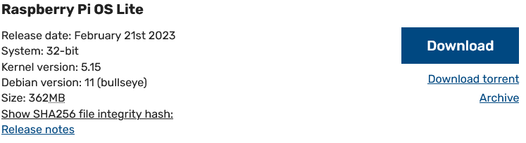
First step is to install Raspberry Pi OS from
https://www.raspberrypi.com/software/operating-systems/
The driver is compatible with kernel versions 5.4, 5.10, 5.15 and 6.1 (32-bit and 64-bit), so download the appropriate Raspberry Pi OS version. Raspberry Pi OS Buster Lite is sufficient, and this guide expects this version to be installed not only for the framebuffer output handling.
For more installation instructions see the Raspberry Pi OS Installation Manual; the procedure depends on the platform type where the OS is going to be installed.
(Original site may look different) Install Raspberry Pi OS by following the instructions provided there
The display shows a login prompt after successful installation. If this is not the case, you have to check your Raspberry Pi OS installation. The most relevant information to succeed can be found at the Raspberry Pi OS website or on the web.
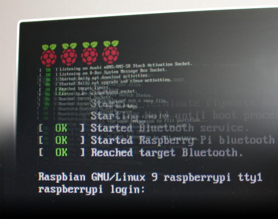
Raspberry Pi OS showing login screen (user is usually pi with password raspberry)
1.2 Connect the MIPI module
Warning
Always disconnect all cables before connecting or disconnecting the MIPI module!
The ends of the MIPI module connector cable is marked with the hardware to connect to. Open the socket connectors first by raising their lid, insert the cable and press their lid back when mounted correctly. You should then not be able to pull the cable out.
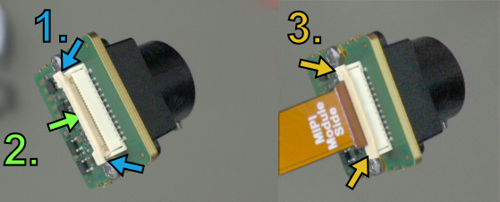
Open the MIPI module socket, put in the cable, close the MIPI module socket
Warning
The connection at this type of socket is not protected against bad alignment, so always check the orthogonality, and if it is bent, correct it! Also watch out for the right orientation of the cable! The MIPI module or the board connected on the other side can be irrevocably damaged if the cable is not inserted the right way, and warranty is lost!
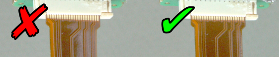
Harmfully angled (left) and good (right) cable fixation
The socket type is also not protected against wrong orientation, so compare your setup to the figures below before switching the power on.

Watch the orientation of the cable (left: bad, right: good)
Connect the MIPI sensor to the socket named CAM1.
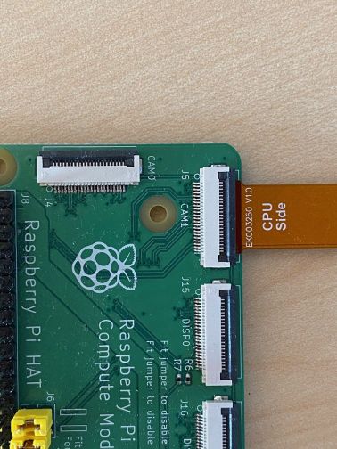
Connect the cable to the CAM1 socket and watch out for the cable orientation
The I²C bus named VC is used for sensor communication and is internally connected to the CAM1 socket's I²C bus pins.
A second sensor can be connected to the socket named CAM0. Its corresponding I²C pins at the J8 GPIO connector are ID_SD and ID_SC. We will use the second I²C bus i2c_arm to connect to the second sensor. Its data lane is at pin GPIO2 while its clock signal resides at pin GPIO3 of the J8 GPIO connector.
Therefore connect the J8 GPIO connector's
- pin named GPIO2 with the pin named ID_SD as well as the
- pin named GPIO3 with the pin named ID_SC.
Moreover two jumpers have to be fitted on the J6 connector.

Connections on CM4IO GPIO header
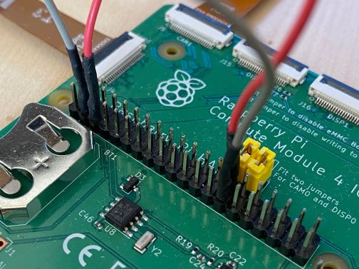
Cable and jumper connections on J8 and J6 headers
Warning
Do not connect other devices to the I²C bus named VC, since it can affect the communication between the camera sensor and the driver!
For example, running the touch screen of the Raspberry PI 7 inch display will lead to communication problems between driver and camera sensor. The display may work with the following line appended to the /boot/config.txt, but test first without connecting it to the Raspberry PI to be sure everything works so far:
disable_touchscreen=1
Reconnect the other peripherials to the Raspberry Pi.
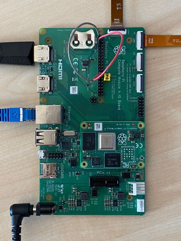
Connection setup
You should have the login prompt back after switching the system on.
Raspbian showing login screen (user is usually pi with password raspberry)
1.3 Optional: Trigger input
If the MIPI sensor supports it, you can trigger it externally for an image capture. To do so, you can use the VC Repeater Board: https://www.vision-components.com/fileadmin/external/documentation/hardware/VC_MIPI_Repeater_Board/index.html
2 Software Setup
2.1 Get the driver and demo code
You can download the driver and demo code from the following links.
- Driver: vc-mipi-driver-bcm2835-dkms_0.2.7_all.zip
- Demo code: vcmipidemo_0.7.0.zip
2.2 Install necessary Raspberry Pi OS packages
Before beginning with the installation, do the following steps first. This requires your Raspberry PI to already have an internet connection; otherwise you have to install the packages mentioned manually, search the web for the procedure needed.
Update the raspberrypi-kernel package and your system by calling:
sudo apt-get update && sudo apt-get upgrade
Reboot.
Install the raspberrypi-kernel-headers and device-tree-compiler package by using the following command:
sudo apt-get install raspberrypi-kernel-headers device-tree-compiler
Test if the version of the running kernel matches the version of the kernel headers, the following command should show the directory for compiling the sensor module kernel module driver:
ls "/usr/src/linux-headers-$(uname -r)"
Install the dkms package with:
sudo apt-get install dkms
2.3 Driver Installation
Note
If you already installed an older version of the driver, an update will not modify the device tree files and the configuration files, in case customers made their own changes. If you wish to update the device tree files and the configuration files together with the driver it is necessary to deinstall the driver first and to delete the device tree files with the following commands:
sudo apt-get purge vc-mipi-driver-bcm2835-dkms
sudo rm -rf /boot/config_vc*
sudo rm -rf /boot/overlays/vc-mipi*
Warning
It is important that the date and time of your Raspberry Pi are set correctly! You can set the date and time using NTP:
sudo apt-get install ntpdate
ntpdate ip_address_of_ntp_server
Or you can use the command "date":
sudo date -s "2021-08-20 09:41:00"
In both cases store the time and date in the hardware clock:
sudo hwclock -w
Copy the driver debian package (vc-mipi-driver-bcm2835-dkms_x.x.x_armhf.deb) to the /tmp folder on the Raspberry Pi.
Install the driver package by calling (replace x.x.x by the current version number):
sudo dpkg -i /tmp/vc-mipi-driver-bcm2835-dkms_x.x.x_armhf.deb
Edit the file /boot/config_vc-mipi-driver-bcm2835.txt (for example with nano with the command: sudo nano /boot/config_vc-mipi-driver-bcm2835.txt).
- choose the correct platform by uncommenting the corresponding line
- choose the correct overlay according to your MIPI module and platform by uncommenting the corresponding line (for the IMX565, IMX566, IMX567, IMX568 please activate the overlay for the IMX568.)
- choose the desired sensor mode (see chapter Sensor modes below for mode description)
- change the IO configuration if necessary (see chapter IO configuration below for IO description)
- activate the self-triggered mode (see chapter Self-triggered mode below)
All these settings can be done for cam0 and cam1 in case you are using a Raspberry Pi CMIO or a VC CMIO.
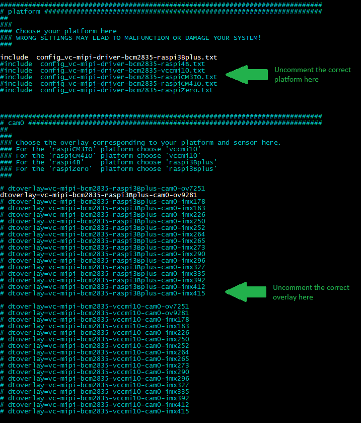
Part 2:
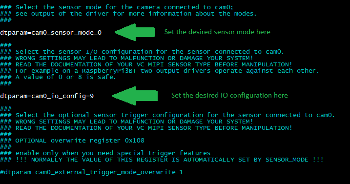
Example of configuration file for the OV9281 MIPI module on a Raspberry Pi 3B+ in sensor mode 0.
Reboot.
Note
For the IMX565, IMX566, IMX567, IMX568 please activate the overlay for the IMX568.
2.4 First Image Acquisition Test
A sensor device should be listed as Video input at the following command output (from the Video4Linux-Control):
v4l2-ctl --all
The following command dumps sensor data:
v4l2-ctl --stream-mmap --stream-count=-1 -d /dev/video0 --stream-to=/dev/null
It will output subsequent lines ending with a frames-per-second information (in the example named [number]) until pressing CTRL-C:
<<<<<<<<<<<<<<<<<<<<<<<<<<<<<<<<<<<<<<<<< [number] fps
<<<<<<<<<<<<<<<<<<<<<<<<<<<<<<<<<<<<<<<<< [number] fps
<<<<<<<<<<<<<<<<<<<<<<<<<<<<<<<<<<<<<<<<< [number] fps
<<<<<<<<<<<<<<<<<<<<<<<^C
2.5 Running the Demo
The demo itself is a program named vcmipidemo and its source code is mainly in the file vcmipidemo.c. However more programs are provided, namely the vcimgnetsrv, a network image server, and its counterpart vcimgnetclient.py. The vcimgnetsrv is started as background service, and the vcmipidemo connects to it. Then you can use the vcimgnetclient.py on your PC to view live captured images.
But for the first run it is better to just run the vcmipidemo and check if it shows the ascii representation. This works without any network cable attached. You can then output the captured image to the framebuffer of the display by using the -f command line switch.
2.5.1 Compile the programs
- Unpack the previously downloaded archive vcmipidemo_x.x.x.zip and copy the folder vcmipidemo to the Raspberry Pi (for example to /home/pi/)
Change to the subdirectory named vcmipidemo/src.
The source directory contains a Makefile to compile the driver. Do so by calling:
make clean all
2.5.2 Execute the demo
Just run the demo itself:
./vcmipidemo
or with framebuffer output:
./vcmipidemo -f
or with live view over ethernet:
./vcimgnetsrv &
./vcmipidemo
For live view over ethernet, execute the vcimgnetclient.py at the client. This needs Python 2 and PyGTK. Install both following packages in this order (Windows):
Note
You can change exposure and gain values by vcmipidemo command line arguments. To get a listing of possible parameters, just call it with a -?:
./vcmipidemo -?
2.6 Switching Sensor Configuration
2.6.1 Sensor modes
The sensor driver provides different modes which support several features. They can be switched by changing values of sensor driver parameters.
To list available parameters of the sensor driver kernel module, you can use the following command:
dmesg
You can also check the table below (Sensor modes description) for a complete list of available sensor modes.
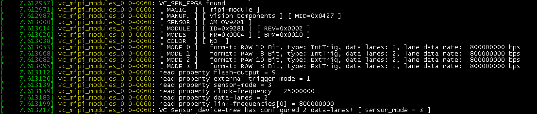
Example of the dmesg command for an OV9281 MIPI module, showing the available sensor modes.
To set the desired mode, edit the file /boot/config_vc-mipi-driver-bcm2835.txt (for example with nano with the command: sudo nano /boot/config_vc-mipi-driver-bcm2835.txt). Change the sensor mode by modifing dtparam:
dtparam=cam0_sensor_mode_1
The number after the underscore is the sensor mode. For mode 0 the correct setting would be dtparam=cam0_sensor_mode_0.
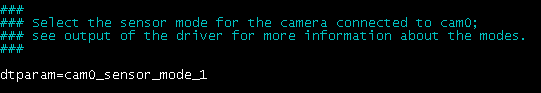
Example of setting the sensor mode to 1 for cam0.
2.6.2 Sensor modes description
This table lists the available modes for all mipi modules.
| VC MIPI OV7251 | Mode | Image format (bits) | Lanes | Capture mode | Resolution |
|---|---|---|---|---|---|
| 0 | 10 | 2 | Streaming | 640x480 | |
| 1 | 8 | 2 | Streaming | 640x480 | |
| 2 | 10 | 2 | External trigger | 640x480 | |
| 3 | 8 | 2 | External trigger | 640x480 |
| VC MIPI OV9281 | Mode | Image format (bits) | Lanes | Capture mode | Resolution |
|---|---|---|---|---|---|
| 0 | 10 | 2 | Streaming | 1280x800 | |
| 1 | 8 | 2 | Streaming | 1280x800 | |
| 2 | 10 | 2 | External trigger | 1280x800 | |
| 3 | 8 | 2 | External trigger | 1280x800 |
| VC MIPI IMX178 | Mode | Image format (bits) | Lanes | Capture mode | Resolution |
|---|---|---|---|---|---|
| 0 | 8 | 2 | Streaming | 3104x2076 | |
| 1 | 10 | 2 | Streaming | 3104x2076 | |
| 2 | 12 | 2 | Streaming | 3104x2076 | |
| 3 | 14 | 2 | Streaming | 3104x2076 | |
| 4 | 8 | 2 | External trigger | 3104x2076 | |
| 5 | 10 | 2 | External trigger | 3104x2076 | |
| 6 | 12 | 2 | External trigger | 3104x2076 | |
| 7 | 14 | 2 | External trigger | 3104x2076 | |
| 8 | 8 | 4 | Streaming | 3104x2076 | |
| 9 | 10 | 4 | Streaming | 3104x2076 | |
| 10 | 12 | 4 | Streaming | 3104x2076 | |
| 11 | 14 | 4 | Streaming | 3104x2076 | |
| 12 | 8 | 4 | External trigger | 3104x2076 | |
| 13 | 10 | 4 | External trigger | 3104x2076 | |
| 14 | 12 | 4 | External trigger | 3104x2076 | |
| 15 | 14 | 4 | External trigger | 3104x2076 |
| VC MIPI IMX183 | Mode | Image format (bits) | Lanes | Capture mode | Resolution |
|---|---|---|---|---|---|
| 0 | 8 | 2 | Streaming | 5440x3648 | |
| 1 | 10 | 2 | Streaming | 5440x3648 | |
| 2 | 12 | 2 | Streaming | 5440x3648 | |
| 3 | 8 | 2 | External trigger | 5440x3648 | |
| 4 | 10 | 2 | External trigger | 5440x3648 | |
| 5 | 12 | 2 | External trigger | 5440x3648 | |
| 6 | 8 | 4 | Streaming | 5440x3648 | |
| 7 | 10 | 4 | Streaming | 5440x3648 | |
| 8 | 12 | 4 | Streaming | 5440x3648 | |
| 9 | 8 | 4 | External trigger | 5440x3648 | |
| 10 | 10 | 4 | External trigger | 5440x3648 | |
| 11 | 12 | 4 | External trigger | 5440x3648 |
| VC MIPI IMX226 | Mode | Image format (bits) | Lanes | Capture mode | Resolution |
|---|---|---|---|---|---|
| 0 | 8 | 2 | Streaming | 3840x3046 | |
| 1 | 10 | 2 | Streaming | 3840x3046 | |
| 2 | 12 | 2 | Streaming | 3840x3046 | |
| 3 | 8 | 2 | External trigger | 3840x3046 | |
| 4 | 10 | 2 | External trigger | 3840x3046 | |
| 5 | 12 | 2 | External trigger | 3840x3046 | |
| 6 | 8 | 4 | Streaming | 3840x3046 | |
| 7 | 10 | 4 | Streaming | 3840x3046 | |
| 8 | 12 | 4 | Streaming | 3840x3046 | |
| 9 | 8 | 4 | External trigger | 3840x3046 | |
| 10 | 10 | 4 | External trigger | 3840x3046 | |
| 11 | 12 | 4 | External trigger | 3840x3046 |
| VC MIPI IMX250 | Mode | Image format (bits) | Lanes | Capture mode | Resolution |
|---|---|---|---|---|---|
| 0 | 8 | 2 | Streaming | 2432x2048 | |
| 1 | 10 | 2 | Streaming | 2432x2048 | |
| 2 | 12 | 2 | Streaming | 2432x2048 | |
| 3 | 8 | 2 | External trigger | 2432x2048 | |
| 4 | 10 | 2 | External trigger | 2432x2048 | |
| 5 | 12 | 2 | External trigger | 2432x2048 | |
| 6 | 8 | 4 | Streaming | 2432x2048 | |
| 7 | 10 | 4 | Streaming | 2432x2048 | |
| 8 | 12 | 4 | Streaming | 2432x2048 | |
| 9 | 8 | 4 | External trigger | 2432x2048 | |
| 10 | 10 | 4 | External trigger | 2432x2048 | |
| 11 | 12 | 4 | External trigger | 2432x2048 |
| VC MIPI IMX252 | Mode | Image format (bits) | Lanes | Capture mode | Resolution |
|---|---|---|---|---|---|
| 0 | 8 | 2 | Streaming | 2048x1536 | |
| 1 | 10 | 2 | Streaming | 2048x1536 | |
| 2 | 12 | 2 | Streaming | 2048x1536 | |
| 3 | 8 | 2 | External trigger | 2048x1536 | |
| 4 | 10 | 2 | External trigger | 2048x1536 | |
| 5 | 12 | 2 | External trigger | 2048x1536 | |
| 6 | 8 | 4 | Streaming | 2048x1536 | |
| 7 | 10 | 4 | Streaming | 2048x1536 | |
| 8 | 12 | 4 | Streaming | 2048x1536 | |
| 9 | 8 | 4 | External trigger | 2048x1536 | |
| 10 | 10 | 4 | External trigger | 2048x1536 | |
| 11 | 12 | 4 | External trigger | 2048x1536 |
| VC MIPI IMX264 | Mode | Image format (bits) | Lanes | Capture mode | Resolution |
|---|---|---|---|---|---|
| 0 | 8 | 2 | Streaming | 2432x2048 | |
| 1 | 10 | 2 | Streaming | 2432x2048 | |
| 2 | 12 | 2 | Streaming | 2432x2048 | |
| 3 | 8 | 2 | External trigger | 2432x2048 | |
| 4 | 10 | 2 | External trigger | 2432x2048 | |
| 5 | 12 | 2 | External trigger | 2432x2048 |
| VC MIPI IMX265 | Mode | Image format (bits) | Lanes | Capture mode | Resolution |
|---|---|---|---|---|---|
| 0 | 8 | 2 | Streaming | 2048x1536 | |
| 1 | 10 | 2 | Streaming | 2048x1536 | |
| 2 | 12 | 2 | Streaming | 2048x1536 | |
| 3 | 8 | 2 | External trigger | 2048x1536 | |
| 4 | 10 | 2 | External trigger | 2048x1536 | |
| 5 | 12 | 2 | External trigger | 2048x1536 |
| VC MIPI IMX273 | Mode | Image format (bits) | Lanes | Capture mode | Resolution |
|---|---|---|---|---|---|
| 0 | 8 | 2 | Streaming | 1440x1080 | |
| 1 | 10 | 2 | Streaming | 1440x1080 | |
| 2 | 12 | 2 | Streaming | 1440x1080 | |
| 3 | 8 | 2 | External trigger | 1440x1080 | |
| 4 | 10 | 2 | External trigger | 1440x1080 | |
| 5 | 12 | 2 | External trigger | 1440x1080 | |
| 6 | 8 | 4 | Streaming | 1440x1080 | |
| 7 | 10 | 4 | Streaming | 1440x1080 | |
| 8 | 12 | 4 | Streaming | 1440x1080 | |
| 9 | 8 | 4 | External trigger | 1440x1080 | |
| 10 | 10 | 4 | External trigger | 1440x1080 | |
| 11 | 12 | 4 | External trigger | 1440x1080 | |
| 12 | 8 | 2 | Streaming | 720x540 (binning) | |
| 13 | 10 | 2 | Streaming | 720x540 (binning) | |
| 14 | 12 | 2 | Streaming | 720x540 (binning) | |
| 15 | 8 | 2 | External trigger | 720x540 (binning) | |
| 16 | 10 | 2 | External trigger | 720x540 (binning) | |
| 17 | 12 | 2 | External trigger | 720x540 (binning) | |
| 18 | 8 | 4 | Streaming | 720x540 (binning) | |
| 19 | 10 | 4 | Streaming | 720x540 (binning) | |
| 20 | 12 | 4 | Streaming | 720x540 (binning) | |
| 21 | 8 | 4 | External trigger | 720x540 (binning) | |
| 22 | 10 | 4 | External trigger | 720x540 (binning) | |
| 23 | 12 | 4 | External trigger | 720x540 (binning) |
| VC MIPI IMX290 | Mode | Image format (bits) | Lanes | Capture mode | Resolution |
|---|---|---|---|---|---|
| 0 | 10 | 2 | Streaming | 1920x1080 | |
| 1 | 10 | 4 | Streaming | 1920x1080 |
| VC MIPI IMX296 | Mode | Image format (bits) | Lanes | Capture mode | Resolution |
|---|---|---|---|---|---|
| 0 | 10 | 1 | Streaming | 1440x1080 | |
| 1 | 10 | 1 | External trigger | 1440x1080 | |
| 2 | 10 | 1 | Streaming | 720x540 (binning) | |
| 3 | 10 | 1 | External trigger | 720x540 (binning) |
| VC MIPI IMX296 C | Mode | Image format (bits) | Lanes | Capture mode | Resolution |
|---|---|---|---|---|---|
| 0 | 10 | 1 | Streaming | 1440x1080 | |
| 1 | 10 | 1 | External trigger | 1440x1080 |
| VC MIPI IMX297 | Mode | Image format (bits) | Lanes | Capture mode | Resolution |
|---|---|---|---|---|---|
| 0 | 10 | 1 | Streaming | 720x540 | |
| 1 | 10 | 1 | External trigger | 720x540 |
| VC MIPI IMX327 C | Mode | Image format (bits) | Lanes | Capture mode | Resolution |
|---|---|---|---|---|---|
| 0 | 10 | 2 | Streaming | 1920x1080 | |
| 1 | 10 | 4 | Streaming | 1920x1080 |
| VC MIPI IMX335 | Mode | Image format (bits) | Lanes | Capture mode | Resolution |
|---|---|---|---|---|---|
| 0 | 10 | 2 | Streaming | 2560x1964 | |
| 1 | 10 | 2 | Streaming | 2560x1964 | |
| 2 | 12 | 2 | Streaming | 2560x1964 | |
| 3 | 12 | 2 | Streaming | 2560x1964 | |
| 4 | 10 | 4 | Streaming | 2560x1964 | |
| 5 | 10 | 4 | Streaming | 2560x1964 | |
| 6 | 12 | 4 | Streaming | 2560x1964 | |
| 7 | 12 | 4 | Streaming | 2560x1964 |
| VC MIPI IMX392 | Mode | Image format (bits) | Lanes | Capture mode | Resolution |
|---|---|---|---|---|---|
| 0 | 8 | 2 | Streaming | 1920x1200 | |
| 1 | 10 | 2 | Streaming | 1920x1200 | |
| 2 | 12 | 2 | Streaming | 1920x1200 | |
| 3 | 8 | 2 | External trigger | 1920x1200 | |
| 4 | 10 | 2 | External trigger | 1920x1200 | |
| 5 | 12 | 2 | External trigger | 1920x1200 | |
| 6 | 8 | 4 | Streaming | 1920x1200 | |
| 7 | 10 | 4 | Streaming | 1920x1200 | |
| 8 | 12 | 4 | Streaming | 1920x1200 | |
| 9 | 8 | 4 | External trigger | 1920x1200 | |
| 10 | 10 | 4 | External trigger | 1920x1200 | |
| 11 | 12 | 4 | External trigger | 1920x1200 |
| VC MIPI IMX412 C | Mode | Image format (bits) | Lanes | Capture mode | Resolution |
|---|---|---|---|---|---|
| 0 | 10 | 2 | Streaming | 4056x3040 | |
| 1 | 10 | 4 | Streaming | 4056x3040 |
| VC MIPI IMX415 C | Mode | Image format (bits) | Lanes | Capture mode | Resolution |
|---|---|---|---|---|---|
| 0 | 10 | 2 | Streaming | 3864x2192 | |
| 1 | 10 | 4 | Streaming | 3864x2192 |
| VC MIPI IMX462 C | Mode | Image format (bits) | Lanes | Capture mode | Resolution |
|---|---|---|---|---|---|
| 0 | 10 | 2 | Streaming | 1920x1080 | |
| 1 | 10 | 4 | Streaming | 1920x1080 |
| VC MIPI IMX565 | Mode | Image format (bits) | Lanes | Capture mode | Resolution |
|---|---|---|---|---|---|
| 0 | 8 | 2 | Streaming | 4128x3008 | |
| 1 | 10 | 2 | Streaming | 4128x3008 | |
| 2 | 12 | 2 | Streaming | 4128x3008 | |
| 3 | 8 | 2 | External trigger | 4128x3008 | |
| 4 | 10 | 2 | External trigger | 4128x3008 | |
| 5 | 12 | 2 | External trigger | 4128x3008 | |
| 6 | 8 | 4 | Streaming | 4128x3008 | |
| 7 | 10 | 4 | Streaming | 4128x3008 | |
| 8 | 12 | 4 | Streaming | 4128x3008 | |
| 9 | 8 | 4 | External trigger | 4128x3008 | |
| 10 | 10 | 4 | External trigger | 4128x3008 | |
| 11 | 12 | 4 | External trigger | 4128x3008 |
| VC MIPI IMX566 | Mode | Image format (bits) | Lanes | Capture mode | Resolution |
|---|---|---|---|---|---|
| 0 | 8 | 2 | Streaming | 2848x2840 | |
| 1 | 10 | 2 | Streaming | 2848x2840 | |
| 2 | 12 | 2 | Streaming | 2848x2840 | |
| 3 | 8 | 2 | External trigger | 2848x2840 | |
| 4 | 10 | 2 | External trigger | 2848x2840 | |
| 5 | 12 | 2 | External trigger | 2848x2840 | |
| 6 | 8 | 4 | Streaming | 2848x2840 | |
| 7 | 10 | 4 | Streaming | 2848x2840 | |
| 8 | 12 | 4 | Streaming | 2848x2840 | |
| 9 | 8 | 4 | External trigger | 2848x2840 | |
| 10 | 10 | 4 | External trigger | 2848x2840 | |
| 11 | 12 | 4 | External trigger | 2848x2840 |
| VC MIPI IMX567 | Mode | Image format (bits) | Lanes | Capture mode | Resolution |
|---|---|---|---|---|---|
| 0 | 8 | 2 | Streaming | 2432x2048 | |
| 1 | 10 | 2 | Streaming | 2432x2048 | |
| 2 | 12 | 2 | Streaming | 2432x2048 | |
| 3 | 8 | 2 | External trigger | 2432x2048 | |
| 4 | 10 | 2 | External trigger | 2432x2048 | |
| 5 | 12 | 2 | External trigger | 2432x2048 | |
| 6 | 8 | 4 | Streaming | 2432x2048 | |
| 7 | 10 | 4 | Streaming | 2432x2048 | |
| 8 | 12 | 4 | Streaming | 2432x2048 | |
| 9 | 8 | 4 | External trigger | 2432x2048 | |
| 10 | 10 | 4 | External trigger | 2432x2048 | |
| 11 | 12 | 4 | External trigger | 2432x2048 |
| VC MIPI IMX568 | Mode | Image format (bits) | Lanes | Capture mode | Resolution |
|---|---|---|---|---|---|
| 0 | 8 | 2 | Streaming | 2432x2048 | |
| 1 | 10 | 2 | Streaming | 2432x2048 | |
| 2 | 12 | 2 | Streaming | 2432x2048 | |
| 3 | 8 | 2 | External trigger | 2432x2048 | |
| 4 | 10 | 2 | External trigger | 2432x2048 | |
| 5 | 12 | 2 | External trigger | 2432x2048 | |
| 6 | 8 | 4 | Streaming | 2432x2048 | |
| 7 | 10 | 4 | Streaming | 2432x2048 | |
| 8 | 12 | 4 | Streaming | 2432x2048 | |
| 9 | 8 | 4 | External trigger | 2432x2048 | |
| 10 | 10 | 4 | External trigger | 2432x2048 | |
| 11 | 12 | 4 | External trigger | 2432x2048 |
2.6.3 IO configuration
Some sensors can be triggered externally and also provide a flash output. These two features can be switched using the cam0_io_config parameter.
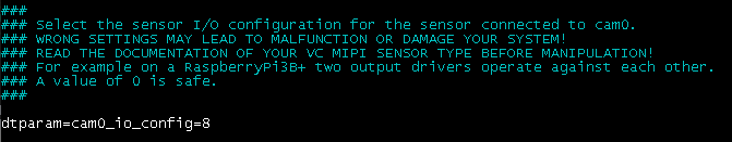
Example of setting the IO configuration to 8 for cam0.
This parameter corresponds to the value written to register 3 on the MIPI module. A value of 0x08 activates the trigger input. A value of 0x09 activates the trigger input and the flash output.
After modifying the sensor mode or the IO configuration, save the changes and reboot.
2.6.4 Self-triggered mode
On some modules the streaming mode does not allow a flash output signal. In this case it is necessary to activate the so-called self-triggered mode (from the user point of view it behaves like the streaming mode). This is done by choosing one of the external trigger modes and additionally overriding the value of the register 0x0108 of the mipi controller.
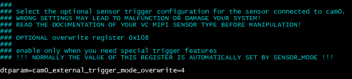
Register 0x108 configuration: set to 4 for self-triggered mode.
A detailed documentation of the mipi controller registers is available on request.
3 Troubleshooting and Background Information
3.1 Q/A
Problem:
Running make fails with an error:
⋮make[1]: *** /lib/modules/4.14.79-v7+/build: No such file or directory. Stop.⋮
Solution:
The system needs the build tools of the kernel to build the sensor driver (which itself is a kernel module). They can be obtained by installing the RaspberryPi Kernel Headers package named raspberrypi-kernel-headers, see https://www.raspberrypi.org/documentation/linux/kernel/headers.md
Problem:
The sensor module driver cannot be started, it shows an error:
⋮[ 4.773298] imx296 0-0060: Error -5 setting default controls[ 4.773346] imx296: probe of 0-0060 failed with error -5⋮
Solution:
Be sure no other device is connected to the I²C bus 0! For example, the touch screen controller of the Raspberry PI display may not be connected.
Check the orientation of the cable at the sensor side as well as at the cpu side. Also check if the cable and the sockets are orthogonal.
3.2 Driver Knowledge
The following tasks have to be done to do an image acquisition with the camera sensor:
- Information about the new sensor hardware and its connector must be provided to the kernel by adding it to the so-called kernel device tree as overlay.
- This device tree overlay must be applied to the kernel device tree.
- For the driver to communicate with the sensor the I²C bus must be set up to connect between the CPU and the MIPI socket.
- The driver itself must be installed as kernel modules.
- Contiguous memory must be reserved for the captured image.
The driver is separated into parts exclusive for the platform, e.g. the Raspi3BPlus as well as generic parts.
The main configuration file for the driver is named:
config_vc-mipi-driver-bcm2835.txt
It should include the platform specific configuration, here the file:
config_vc-mipi-driver-bcm2835-raspi3Bplus.txt
and also refer to the sensor overlays (see the following) you would like to use. Overlays can be found relative to the configuration file at the ./overlays/ directory.
3.2.1 Providing device tree overlays
The so-called kernel device tree overlay contains information about the socket and periphery where the mipi module is connected to.
Here are the steps to compile a device tree overlay by yourself:
We assume to compile an example overlay file named
example123-overlay.dts
Install the device-tree-compiler package via:
sudo apt-get install device-tree-compiler
Compile the dtbo kernel device tree overlay binary representation by using the following command:
dtc -@ -I dts -O dtb -o example123.dtbo example123-overlay.dtsCopy the binary to
/boot/overlays/example123.dtbo
3.2.1.1 Telling the RTOS to use the device tree overlay
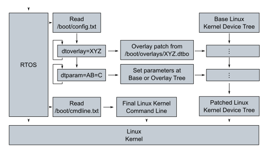
Raspbian Boot overview
Before starting the linux kernel, the Raspberry Pi first boots a real-time operating system (RTOS) on the GPU. This RTOS looks into the file /boot/config.txt. It loads a default Kernel device tree and patches it by overlaying the device tree parts listed by the dtoverlay entries at the file /boot/config.txt. To add new information to the device tree this config-file (or a therein included file) needs the following entry:
dtoverlay=example123
The device tree will then be modified by the overlay at
/boot/overlays/example123.dtbo
before the linux kernel is run.
To check the behaviour of the RTOS one can look at the output by the following command:
sudo vcdbg log msg
Example
After reboot the applied overlays can be shown by executing the following command:
sudo vcdbg log msg 2>&1 | grep '^[0-9\.]\+: Loaded overlay'
Here is a sample output:
002143.555: Loaded overlay 'example123'
A deeper insight into the device tree overlays and parameters can be found at https://www.raspberrypi.org/documentation/configuration/device-tree.md
3.2.2 Set up the I²C bus for driver-sensor communication
For the RaspberryPi 3B+ there is only one socket available, so there is no need to change the CSI port information at a device tree overlay provided.
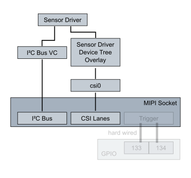
Trigger input is hardwired to pin 133, trigger output to pin 134, unuseable/unaccessible.
Note
On this Raspberry PI model the pins used for trigger input and output are hard-wired to some GPIO, so external triggering is not possible (no access).
Warning
Hardware will be damaged and warranty lost if you use pins as outputs where the sensor has its own flash output, so double-check before you (if you are able to) access the trigger gpio pins! Don't activate sensor flash or sync output (e.g via the dtparam cam*_io_config) if the wires are connected to an output, for example at a RaspberryPi3B+!
The sensor driver needs to communicate via the I²C Bus named VC. To be able to access it, assigning it to the CPU is mandatory.

Raspbian I²C connection: Influence of the parameter dtparam=i2c_vc=on
The I²C bus is assigned by the RTOS. So the file /boot/config_vc-mipi-driver-bcm2835-raspi3Bplus.txt has an entry:
dtparam=i2c_vc=on
It changes the physical I²C bus VC accessor from the default, the GPU, to the CPU. The referred overlay vc-mipi-bcm2835-raspi3Bplus-i2c0 makes it accessible for linux over GPIO pins.
Note
Some hardware like the touch display demands exclusiveness over the I²C Bus VC or their drivers assume the I²C Bus VC is connected to the RTOS. Since the sensor driver must communicate with the sensor module connected to the MIPI socket, neither the exclusiveness nor the RTOS connectedness is given. So the I²C bus VC cannot be used for other purposes when the sensor is attached.
Example
After reboot the dtparam line can be shown by executing the following command:
sudo vcdbg log msg 2>&1 | grep '^[0-9\.]\+: dtparam:'
Here is a sample output:
002077.358: dtparam: audio=on
002096.467: dtparam: i2c_vc=on
3.2.3 Providing the sensor driver as kernel module
Here are the steps to compile the kernel modules by yourself:
After installation of the DKMS module the driver will be found at a subdirectory of the folder /usr/src/:
vc-mipi-driver-bcm2835-versionnumber
Copy it to a new place and change to that new place, since the previous mentioned subdirectory is part of the DKMS package management! Be aware, that after a new kernel version installation, the DKMS will rebuild the driver. Check where the sources for that rebuild lies to have your customized setup after the kernel update.
The source directory contains a Makefile to compile the driver. Do so by calling:
make clean all
The directory then contains the driver as several modules. They must be copied to their place
- *.ko to /lib/modules/$(uname -r)/kernel/drivers/media/i2c/
- *.txt to /boot/
- overlays/*.dtbo to /boot/overlays/
Afterwards the new modules must be registered by calling depmod -a and the main configuration file must be included at the /boot/config.txt.
All this can be also done by calling:
make install
debian/postinst
The module drivers will then be loaded by calling the following commands in that order (or automatically at boot):
modprobe vc_mipi_modules_0modprobe bcm2835-unicam
Example
After reboot you can display the output of the vc_mipi_imx296 kernel module by executing the following command:
dmesg | grep '^[^]]*\] vc_mipi_modules_0'
Here is a sample output which will be different at your setup:
3.2.4 Reserving Contiguous Memory for the Image Captures
In contrast to the normally used non-contiguous memory the capture hardware needs a contiguous memory region to transfer pixel data to by using direct memory access (DMA).
To reserve other than 128MByte of memory for capturing images, edit the overlay file named
vc-mipi-common-memory-contiguous-overlay.dts
and change its size entry, for example to use 64MiB:
size = <0x4000000>; /* 64MiB */
Compile the .dts file and copy its .dtbo file to /boot/overlays/.
After reboot the kernel message line beginning with Memory: will show an updated entry (last one):
[ 0.000000] Memory: 881620K/970752K available (8192K kernel code, 653K rwdata, 2220K rodata, 1024K init, 822K bss, 23596K reserved, 65536K cma-reserved)
Example
After reboot you can show the line by executing the following command:
dmesg | grep '^[^]]*\] Memory:'
Here is a sample output which will look slightly different at your setup:
[ 0.000000] Memory: 817108K/970752K available (7168K kernel code, 576K rwdata, 2076K rodata, 1024K init, 698K bss, 22572K reserved, 131072K cma-reserved)