|
VCLinux Library Documentation
3.11.2
|
|
VCLinux Library Documentation
3.11.2
|
 Collaboration diagram for Image Acquisition:
Data Structures | |
| union | VCFlashSelector |
| Flash Output Selector. More... | |
| struct | VCSenCustomCalls |
| Sensor/FPGA Customizations (ignore at standard cameras). More... | |
| union | VCSenCustomInit |
| Special Sensor Settings and Data. More... | |
| struct | VCSenInit |
| Sensor Settings only configurable during Initialization. More... | |
| struct | VCSenExternal |
| External optional delivered Values of Sensor Settings Struct. More... | |
| struct | VCSenCaptInfo |
| Sensor Capture Data. More... | |
| struct | VCSenVolatile |
| Volatile Values of Sensor Settings Struct. More... | |
| struct | VCSenDesc |
| Sensor Description. More... | |
| union | VCSenCustom |
| Special Sensor Settings and Data. More... | |
| struct | VCSenCfg |
| Sensor Settings. More... | |
| struct | VCTrgInit |
| Trigger Settings only configurable during Initialization. More... | |
| struct | VCTrgDesc |
| Trigger Description. More... | |
| struct | VCTrgCfg |
| Trigger Settings. More... | |
| struct | VCCaptDesc |
| Capture Slot Description. More... | |
| struct | VCCaptCfg |
| Capture Slot Settings. More... | |
Macros | |
| #define | NULL_VCFlashSelector { .whole = 0x00000000 } |
| #define | VCFlashSelector_Default { .whole = 0x80000000 } |
| #define | VCSenInit_Default { 0,0,0, SENSYNC_SYNC, IMAGE_UNSET, 0, {0}, VCSenCustomCalls_Default, NULL_VCSenCustomInit } |
| Sensor Initialization Default Settings. More... | |
| #define | VCSenCfg_Default(d) |
| Sensor Configuration Default Settings. More... | |
| #define | VCTrgInit_Default { TRGMODE_EDGE } |
| Trigger Initialization Default Settings. More... | |
| #define | VCTrgCfg_Default |
| Trigger Config Default Settings. More... | |
| #define | str_VCErrCpt(e) |
| Error Code String for Capture Struct. More... | |
Functions | |
| I32 | vc_capt_init (VCCaptCfg *cptNew, VCCamCfg *cam, VCTrgInit *trgInit, VCSenInit *senInitArr) |
| Initializes a Standard Capture Setup used for Image Acquisitions. More... | |
| I32 | vc_capt (VCCaptCfg *cpt) |
| Takes a Picture. More... | |
| I32 | vc_capt_deinit (VCCaptCfg *cpt) |
| Deinitializes the Capture Configuration used for Image Acquisitions. More... | |
| I32 | vc_capt_init_clone (VCCaptCfg *cptSrc, VCCaptCfg *cptTgt) |
| Initializes a new Capture Setup by Cloning. More... | |
| I32 | vc_capt_request (VCCaptCfg *cpt) |
| Requests for an Image Acquisition. More... | |
| I32 | vc_capt_wait (VCCaptCfg *cpt, I64 timeout_ms) |
| Waits for an Image Acquisition to be Finished. More... | |
| I32 | vc_capt_remove_all_requests (I32 cptCnt, VCCaptCfg *allCpt) |
| Removes any outstanding image acquisition requests. More... | |
| void | vc_capt_print (VCCaptCfg *cpt) |
| Prints out the Values of the VCCaptCfg Struct to the Terminal. More... | |
| I32 | vc_capt_verify (VCCaptCfg *cpt) |
| Verifies Capture Struct Readiness for Image Acquisition. More... | |
| I32 | vc_capt_init_raw (VCCaptCfg *cptNew, VCCamCfg *cam, VCTrgInit *cptInit) |
| Initializes the Capture Setup used for Image Acquisitions. More... | |
| I32 | vc_capt_init_sen_add (VCCaptCfg *cpt, U32 senPortNr, VCSenInit *senInit, VCTrgInit *trgInit) |
| Adds a Sensor to a pre-initialized Capture Configuration. More... | |
| void | vc_capt_sen_shutter_set_all (VCCaptCfg *cpt, U32 shutter) |
| Sets the Shutter Time of All Sensors at the Capture Struct to the given Value. More... | |
| void | vc_capt_sen_gain_set_all (VCCaptCfg *cpt, F32 gain) |
| Sets the Gain Value of All Sensors at the Capture Struct to the given Value. More... | |
| I32 | vc_capt_sen_lut_set_all (VCCaptCfg *capt, U8 *lut, I32 entries) |
| Sets the sensor grey value lookup table of all sensors at the capture struct to the given value. More... | |
| I32 | vc_capt_sen_lut_reset_all (VCCaptCfg *capt) |
| Sets the sensor grey value lookup table of all sensors at the capture struct to its initial state. More... | |
| I32 | vc_sen_shutter_calculate (VCSenCfg *sen, U32 requestShutter, U32 *calculatedShutter) |
| Calculates the Exact Shutter Time used for the Image Acquisition. More... | |
| I32 | vc_sen_lut_set (U8 *lut, I32 entries, VCSenCfg *sen) |
| Sets sensor grey value lookup table. More... | |
| I32 | vc_sen_lut_reset (VCSenCfg *sen) |
| Resets sensor grey value lookup table to its initial state. More... | |
| void | vc_sen_cfg_to_default (VCSenCfg *sen) |
| Sets the Sensor Configuration to Default Values. More... | |
| void | vc_sen_img_to_default (VCSenCfg *sen) |
| Sets the Image Variable at the Sensor Configuration to Default Values. More... | |

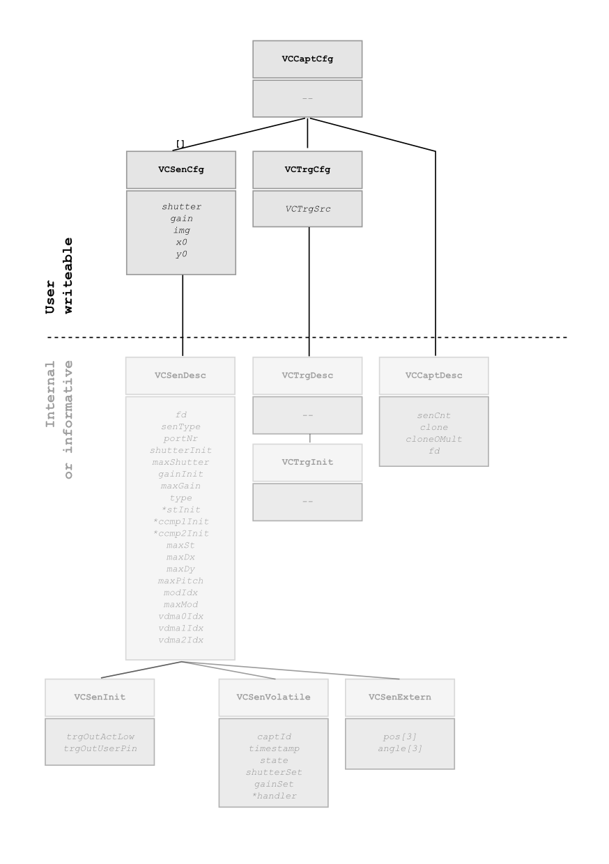
A capture configuration holds information about the triggering input and the sensors recording photons at the moment of the trigger event. This capture configuration structure, VCCaptCfg, will be initialized by the function vc_capt_init(). Each added sensor becomes accessible over an index value starting with 0. The initialisation sets the sensor configuration to default values which can be modified afterwards, for example, to change the shutter time of the first sensor to 10000us, you can write cpt.sen[0].shutter = 10000 (which is for index 0 equivalent to cpt. sen->shutter = 10000). An order for an image acquisition is placed by providing the complete capture configuration to the function named vc_capt_request(). Depending on the configuration, the image acquisition will be served at the next possible moment, or the capture will be started after the input trigger occurs. To ensure, that the image acquisition has been completed, the function vc_capt_wait() must always be used to block until the acquisition finished or until a timeout occurs which may be set to stay out forever. If no timeout functionality is needed, you can replace vc_capt_request() and vc_capt_wait() calls by using the helper function vc_capt(). After an acquisition is finished, the result image can be accessed by its image struct cpt.sen[0].img. For proper deinitialization, the function vc_capt_deinit() must be called before leaving the program. The function vc_capt_init() requires a previously initialized VCCamCfg structure, which can be done at once by calling the wrapper function vc_cam_init().
The shutter time and the gain can be set via the following sensor parameters, assuming the index number of the sensor to be configured is zero:
cpt.sen[0].shutter cpt.sen[0].gain Those shutter times may be rounded to the next possible value. You can get the real shutter time by calling the function named vc_sen_shutter_calculate().
Their maximum values are provided through the VCSenDesc struct:
cpt.sen[0].d.maxShutter cpt.sen[0].d.maxGain To set the shutter or gain values at once for all the sensors of one capture, the convenience functions vc_capt_sen_shutter_set_all() and vc_capt_sen_gain_set_all() can be used.
You can specify the sensor ROI by changing the following values, assuming the index number of the sensor to be configured is zero:
cpt.sen[0].x0, Top left coordinate's x valuecpt.sen[0].y0, Top left coordinate's y valuecpt.sen[0].img.dx: ROI widthcpt.sen[0].img.dy: ROI heightYou may get the default (= maximum) dimensions back from the description cpt.sen[0].d.maxDx and cpt.sen[0].d.maxDy. The top left ROI coordinate is (0,0). The VCSenCfg struct documentation may contain additional information for the parameters.
Please note that sensors may have specific restrictions to the ROI, like, for example, dx must be dividable by 32, or for color sensors x0, y0, dx and dy should be dividable by 2 if you need to use their correct bayer pattern color information. The important dividability information contain the parameters cpt.sen[0].d.stepDx, cpt.sen[0].d.stepDy and cpt.sen[0].d.stepPitch.
For a better memory usage and a possible speed up, one can limit the maximum sensor image size at the sensor initialization phase. To do so, you can pass your maximum values for image dx, dy and pitch, to the VCSenInit struct. The default values (at VCSenInit_Default) for the limiting values are zero, which imply the meaning of an unset value. A zero value will lead to a replacement with the sensor's maximum value. For a limitation in x direction, please also set the maxPitch value to the appropriate maxDx value. The initial dimensions of the sen[].img will be set to your limitation wish (Be aware, that not all values are applicable).
For example, if you only need a small band of 256 px height, you can change the maxDy value at the defaulted VCSenInit struct before calling vc_cam_init() (or vc_capt_init_sen_add()) and pass it to the function:

The basic idea for doing image acquisitions to more than one buffer per sensor is first to set up and configure a capture configuration and then use it for other capture slots as a blueprint. The initialization and transfer of all settings to a new capture configuration is done by using the function named vc_capt_init_clone().

As you can see at the example code, each parallel capture request needs its own capture struct, so you have to clone the initial configuration to reserve more memory for the acquisition.
The example code requests an image first for all defined capture configurations, then waits for the oldest request to finish, and if that capture has been received, it also peeks for the following captures if they are ready, too. Peeking is an important step, since receiving all captured images so far allows us to insert every received capture later for new image acquisitions: Since linux is not a real-time operating system, there may be a sleep time of the capture program at any time. So, for example, to prevent unavailable capture requests for an incoming external trigger signal, the capture queue must not underrun. If there was no peeking for the next captures, one can get a slow drift to capture queue underrun, since, after processing, one is just able to re-enqueue only one capture request and not all available. By having all available captures after peeking, images may be pre-processed and selected or ignored for processing if ever processing speed problems occur. Re-enqueuing the whole bunch of captures fills the capture queue buffer again to (perhaps almost) it's maximum.
If further priority of the image acquisition task is needed, it can be raised by moving the capture process to the real-time scheduler queue, for example, by starting the program with the command chrt the following way (see it's man page for more information):
chrt 30 <progname>
More can be done by separating the program into the capture and the processing part, and let distinct cpu cores do the respective parts, see the command taskset and its man page for more information.
The parameters cpt.sen[0].subsmplX and cpt.sen[0].subsmplY describe the subsampling rate for the sensor pixels. The parameters cpt.sen[0].binX and cpt.sen[0].binY describe the binning rate for the sensor pixels. For example, a value of 4 of either subsampling or binning will put only every fourth pixel to the capture image cpt.sen[0img. On most systems these values must be equal to a power of two. The standard value, 1, means that every single pixel is used.

Since sooner or later one must know the size of the outcoming pixel width, we decided the img.dx and img.dy values must be set to the image (not the sensor) pixel width, so you can use that image later easily as an input for the functions, since its dimensions are set right. Naturally you will get an error, if you only raise, for example, the subsmplMaxX/Y on a full-sensor-sized image without applying the correct divided dimensions to the img.dx and img.dy parameters. The x0 and y0 parameters also operate on the target image, i.e. the accessible sensor pixel's coordinates are always a multiple of the subsampling and binning factor.
Not each sensor supports binning during subsampling, check cpt.sen[0].d.binAndSubsmplIff1 for it.
As an example, the formula for the resulting sensor pixel width is:
sensor_pixel_width = img->dx * cpt.sen[0].binX * cpt.sen[0].subsmplX
The description cpt.sen[0].d.subsmplMaxX and cpt.sen[0].d.subsmplMaxY describe the maximum possible values, cpt.sen[0].d.subsmplSquareIff1 encodes the use of subsmplMaxX for both, x and y direction, if and only if it's value equals one; cpt.sen[0].d.subsmplPower2Iff1 defines if subsmplX and subsmplY must be a power of 2.
The description cpt.sen[0].d.binMaxX and cpt.sen[0].d.binMaxY describe the maximum possible values, cpt.sen[0].d.binSquareIff1 encodes the use of binMaxX for both, x and y direction, if and only if it's value equals one; cpt.sen[0].d.binPower2Iff1 defines if binX and binY must be a power of 2.
Color cameras usually output their image as IMAGE_CBCR444: The first channel img->st stores the luminance, while the other both channels img->ccmp1 and img->ccmp2 contain the chroma information, see Types of Image Data for more information. To get the RGB or Bayer representation, the img->type at the VCSenCfg struct has to be set before capturing to the corresponding type, for example:
cpt.sen[0].img.type  = IMAGE_RGB;
cpt.sen[0].img.type  = IMAGE_BAYER;

To choose the sensor input/output trigger signals, the corresponding GPIO Nr. must be determined and assigned by the supporting program named vcio. More information can be found at the help of the program, if you run it with no command line parameter, it will show how to do it. At a multi-sensor-system, be sure to assign the trigger to all sensors, otherwise it would wait for the unassigned trigger forever.
Cameras with two or more sensors can either trigger all sensors simultaneously, or each sensor separately. To do so, the sensors need separate capture structs, since a capture is only finished until all embedded sensors in the capture struct took a picture. Also the input triggers for the sensors should be separated to have them work independently.

See the demo code below to see how it works. For simplicity reason, there are no multiple captures for double buffering purposes, but this code can be extended by combination with the double buffering example.
The capture struct seems to be a bit confusing due to its constellation. All internal data is kept behind '*Desc' structs, at first just ignore everything behind a parameter named 'd'. However we tried to provide valuable information which otherwise would have to be kept simultaneously, like the maximum allowed image width. This and other information can be found behind the 'd's. Never modify anything in areas which are of internal use, since it leads to unpredictable behaviour!
| union VCFlashSelector |
You can select the flash outputs for the sensor recording herewith. The settings done at the vcio program will be ORed with these settings. Also differing settings of the individual sensors will be logically ORed.
The pin direction must be set right, e.g. by the vcio tool in order to get a flash output signal. Also the FPGA Firmware version must be new enough.
The default setting for the flash output is the TrigOut pin to be active, all others inactive.
| Data Fields | ||
|---|---|---|
| U32 | whole |
Complete Bitfield Representation |
| struct VCFlashSelector | set | |
| struct VCSenCustomCalls |
This structure keeps sensor and fpga customizations (ignore at standard cameras).
Data Fields | |
| VCCustomId | customId |
| I32(* | cInitAlloc )(struct _VCSenCfg *sen, void **cInit) |
| I32(* | cInitFree )(struct _VCSenCfg *sen, void **cInit) |
| I32(* | cInitCopy )(struct _VCSenCfg *senSrc, void *cInitSrc, struct _VCSenCfg *senTgt, void *cInitTgt) |
| I32(* | cInitDefault )(struct _VCSenCfg *sen, void *cInit) |
| I32(* | cAlloc )(struct _VCSenCfg *sen, void **c, void *cInit) |
| I32(* | cFree )(struct _VCSenCfg *sen, void **c, void *cInit) |
| I32(* | cCopy )(struct _VCSenCfg *senSrc, void *cSrc, void *cInitSrc, struct _VCSenCfg *senTgt, void *cTgt, void *cInitTgt) |
| I32(* | cDefault )(struct _VCSenCfg *sen, void *c, void *cInit) |
| I32(* | init )(struct _VCSenCfg *sen, void *c, void *cInit) |
| I32(* | deinit )(struct _VCSenCfg *sen, void *c, void *cInit) |
| I32(* | prepare )(struct _VCSenCfg *sen, void *c, void *cInit) |
| I32(* | finalize )(struct _VCSenCfg *sen, void *c, void *cInit) |
| I32(* | verify )(struct _VCSenCfg *sen, void *c, void *cInit) |
| VCCustomId customId |
If customId fits, the following function pointers will be used instead of the original
| I32(* cInitAlloc) (struct _VCSenCfg *sen, void **cInit) |
If customId fits, this function will be used to allocate memory for the cInit Initialization Structure
| I32(* cInitFree) (struct _VCSenCfg *sen, void **cInit) |
If customId fits, this function will be used to free memory of the cInit Initialization Structure
| I32(* cInitCopy) (struct _VCSenCfg *senSrc, void *cInitSrc, struct _VCSenCfg *senTgt, void *cInitTgt) |
If fpgaId fits, this function will be used to copy the cInit Initialization Structure
| I32(* cInitDefault) (struct _VCSenCfg *sen, void *cInit) |
Writes Default Values to the Special Settings Initialization Structure
| I32(* cAlloc) (struct _VCSenCfg *sen, void **c, void *cInit) |
If customId fits, this function will be used to allocate memory
| I32(* cFree) (struct _VCSenCfg *sen, void **c, void *cInit) |
If customId fits, this function will be used to free memory
| I32(* cCopy) (struct _VCSenCfg *senSrc, void *cSrc, void *cInitSrc, struct _VCSenCfg *senTgt, void *cTgt, void *cInitTgt) |
If fpgaId fits, this function will be used to copy the special pointer
| I32(* cDefault) (struct _VCSenCfg *sen, void *c, void *cInit) |
Writes Default Values to the Special Settings Struct
| I32(* init) (struct _VCSenCfg *sen, void *c, void *cInit) |
If customId fits, this function will be used to initialize memory and fpga modules
| I32(* deinit) (struct _VCSenCfg *sen, void *c, void *cInit) |
If customId fits, this function will be used to deinitialize memory and fpga modules
| I32(* prepare) (struct _VCSenCfg *sen, void *c, void *cInit) |
If customId fits, this function will be used to setup fpga modules for image acquisition
| I32(* finalize) (struct _VCSenCfg *sen, void *c, void *cInit) |
If customId fits, this function will be used to finish setup after image acquisition
| I32(* verify) (struct _VCSenCfg *sen, void *c, void *cInit) |
If customId fits, this function will be used to verify settings
| union VCSenCustomInit |
This union points to special settings and data for each sensor, for example, the laser line data and selector settings of a Nano-3D Z. Mandatory is the first element of a custom init struct to be of type VCCustomId with the same value as being used by the VCSenCustomCalls and the custom struct at VCSenCustom.
| struct VCSenInit |
This structure keeps sensor settings which are only configurable during Initialization.
Note, that on special devices, the fitting custom is applied automatically if the custom's fpgaId differ from the device's.
Collaboration diagram for VCSenInit:| Data Fields | ||
|---|---|---|
| I32 | maxDx |
User Limit for Maximum Horizontal Buffer Pixel Count (limits img.dx), at a Value of 0, the Sensor Maximum Value is being used |
| I32 | maxDy |
User Limit for Maximum Vertical Buffer Pixel Count (limits img.dy), at a Value of 0, the Sensor Maximum Value is being used |
| I32 | maxPitch |
User Limit for (Stride) Pixel Count to Next Pixel in Vertical Direction, at a Value of 0, the Sensor Maximum Value is being used |
| VCSenSync | sync |
Synchronize synchronization behaviour |
| U32 | imgType |
To be done. For Bayer Sensors, one can choose IMAGE_BAYER to prevent allocation of 3 channels. Then, however, one cannot change to other types during operation. |
| I8 | GRRIff1 |
Supported rolling shutter sensors switch to a so-called "global reset mode", a whole-exposure-time integration mode which needs you to flash in a dark environment. |
| char | pathUndistort[36] |
Reserved for later use. |
| VCSenCustomCalls | custom |
Defines the Customisation, e.g. by |
| VCSenCustomInit | cInit |
Custom Settings only configurable during initialization, e.g. by modified |
| struct VCSenExternal |
| struct VCSenCaptInfo |
This structure keeps data for each sensor capture.
| Data Fields | ||
|---|---|---|
| U32 | infoCount |
Total Written Count of 32 Bit Capture Information. |
| U32 | captId |
Image acquisition number from capture request call. |
| U64 | timestampTicks |
Timestamp of Image Acquisition since System Startup in Ticks. Convert to seconds using: timestamp/fpgaClkHz. Main purpose is relative capture time measurement with FPGA quartz accuracy so this FPGA-timestamp may differ and drift from the system clock, also consider the non-realtimeness of Linux if you (re-)calibrate. |
| U32 | reserved1 |
Reserved for later use. |
| U32 | encoderPos |
Encoder position (only available at Nano-3D Z). |
| U32 | reserved[26] |
Reserved for later use. |
| struct VCSenVolatile |
This structure keeps volatile data for each sensor.
Collaboration diagram for VCSenVolatile:| Data Fields | ||
|---|---|---|
| I32 | requestCaptId |
Image acquisition number from capture request call |
| VCSenState | state |
Current Processing State |
| VCFPGAModCfg * | mod |
FPGA Module Configuration |
| VCSenCaptInfo * | captInfo |
Internal Capture Request Handler |
| struct VCSenDesc |
This structure keeps Sensor descripting information. Never change anything in here, also not in substructures!
Collaboration diagram for VCSenDesc:| Data Fields | ||
|---|---|---|
| VCSenVolatile | v |
Keeps information about the progress. |
| VCSenExternal | e |
Description of Settings filled externally. |
| I32 | fd |
Sensor Access File Handle |
| I32 | fdCtl |
Sensor Access File Handle |
| I32 | fdMem |
Contiguous Memory Access |
| VCCamType | camType |
Camera Type |
| VCSenType | senType |
Sensor Type |
| I32 | portNr |
Sensor Internal Access Number |
| VCFPGAId | fpgaId |
FPGA Identifier |
| U32 | shutterInit |
Default Initial Shutter Time |
| U32 | maxShutter |
Maximum Allowed Shutter Time |
| F32 | gainInit |
Default Initial Gain Value |
| F32 | maxGain |
Maximum Allowed Gain Value |
| U32 | typeInit |
Sensor Pixel Data Encoding |
| U8 * | stInit |
Initial Address |
| U8 * | ccmp1Init |
Initial Address |
| U8 * | ccmp2Init |
Initial Address |
| I32 | senDx |
Maximum Horizontal Sensor Pixel Count |
| I32 | senDy |
Maximum Vertical Sensor Pixel Count |
| I32 | senPitch |
(Stride) Pixel Count to Next Pixel in Vertical Direction |
| I32 | maxDx |
Maximum Horizontal Buffer Pixel Count (limits img.dx) |
| I32 | stepDx |
Remainderless Divisor of Horizontal Buffer Pixel Count |
| I32 | maxDy |
Maximum Vertical Buffer Pixel Count (limits img.dy) |
| I32 | stepDy |
Remainderless Divisor of Vertical Buffer Pixel Count |
| I32 | maxPitch |
(Stride) Pixel Count to Next Pixel in Vertical Direction |
| I32 | stepPitch |
Remainderless Divisor of (Stride) Pixel Count Pitch |
| I32 | binAndSubsmplIff1 |
If 1 binning and subsampling may be used simultaneously, may have limitations |
| I16 | binSquareIff1 |
If 1 binX will be used as binY, and binY is ignored |
| I16 | binPower2Iff1 |
If 1 binX/Y must be a power of two, e.g. 1,2,4,8,... |
| I32 | binMaxX |
Binning Factor Max Value for Horizontal Direction |
| I32 | binMaxY |
Binning Factor Max Value for Vertical Direction |
| I16 | subsmplSquareIff1 |
If 1 subsmplX will be used as subsmplY, and subsmplY is ignored |
| I16 | subsmplPower2Iff1 |
If 1 subsmplX/Y must be a power of two, e.g. 1,2,4,8,... |
| I32 | subsmplMaxX |
Subsampling Factor Max Value for Horizontal Direction |
| I32 | subsmplMaxY |
Subsampling Factor Max Value for Vertical Direction |
| VCSenFlip | flipability |
All available values for the flip value at |
| U64 | fpgaClkHz |
Use for Timestamp Conversion |
| U64 | senClkHz |
Sensor Clock |
| U32 | imageSMClks |
Internal Conversion Factor |
| U8 * | physBase |
Reference Address, Unchanged by Cloning Capture Struct |
| U32 | physBaseBytes |
Bytes Useable for Image Aqcuisition Data at |
| U8 * | physImg |
Sensor Data Initial Address |
| U32 | physImgBytes |
Bytes Useable for Image Aqcuisition Data at |
| U8 * | virtImg |
Sensor Data Initial Address |
| U16 ** | modIdx |
FPGA Module Configuration Module Cfg Lookup [i][Name|Idx] |
| U16 | maxMod |
FPGA Module Configuration |
| VCSenInit | init |
Description of Initialization Settings. |
| union VCSenCustom |
This union points to special settings and data for each sensor, for example, the laser line data and selector settings of a Nano-3D Z. Mandatory is the first element of a custom struct to be of type VCCustomId with the same value as being used by the VCSenCustomCalls and the custom init struct at VCSenCustomInit.
| Data Fields | ||
|---|---|---|
| void * | unknown |
may be used as a generic handle |
| struct _VCNano3dZ * | nano3dz |
if settings/data are for a VCNano3d Z camera |
| struct _VCCustomBCZ * | bcz |
if settings/data are for a BC Z camera |
| struct VCSenCfg |
This structure keeps settings for each sensor. We will initialize it, but not change anything in it except it is in the VCSenDesc struct.
Do not change parameters between calling vc_capt_request() and vc_capt_wait() for future compatibility reasons; the state of the corresponding VCSenVolatile struct d->v is not SENSTATE_IDLE during that period.
Collaboration diagram for VCSenCfg:| Data Fields | ||
|---|---|---|
| U32 | shutter |
Exposure Time in Microseconds, also see vc_sen_shutter_calculate(). |
| F32 | gain |
Gain Value, values below |
| image | img |
Captured Image |
| I32 | x0 |
ROI x Coordinate of Upper Left Point, may generate wrong colored images on color sensors if not multiple of 2. |
| I32 | y0 |
ROI y Coordinate of Upper Left Point, may generate wrong colored images on color sensors if not multiple of 2. |
| I32 | binX |
Pixel Binning in Horizontal Direction, may be limited to powers of 2 |
| I32 | binY |
Pixel Binning in Horizontal Direction, may be limited to powers of 2 |
| I32 | subsmplX |
Pixel Subsampling in Horizontal Direction, may be limited to powers of 2 |
| I32 | subsmplY |
Pixel Subsampling in Horizontal Direction, may be limited to powers of 2 |
| VCSenFlip | flip |
Pixel Mirroring or 180 deg Rotation, may add some time for switching depending on sensor. |
| VCFlashSelector | flash |
Flash ports active (logically ORed) while image is exposed. |
| U32 | preDelayNs |
Delay between trigger signal and image acquisition start in nanoseconds. There is a post time span needed to transfer the image to memory which may be important for periodic image acquisitions of a specific frequency, also see vc_sen_preDelayNS_calculate(). |
| VCSenDesc | d |
Read-Only Sensor Description |
| VCSenCustom | c |
Special Settings: To access data on special cameras, e.g. the Nano-3D Z |
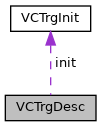
| struct VCTrgInit |
This structure keeps trigger settings which are only configurable during Initialization.
| Data Fields | ||
|---|---|---|
| VCTrgMode | mode |
Trigger Sensitivity |
| struct VCTrgDesc |
This structure keeps trigger descripting information. Never change anything in here, also not in substructures!
Collaboration diagram for VCTrgDesc:| Data Fields | ||
|---|---|---|
| VCTrgInit | init |
Description of Initialization Settings. |
| struct VCTrgCfg |
| struct VCCaptDesc |
This structure keeps Capture Slot descripting information. Never change anything in here, also not in substructures!
| Data Fields | ||
|---|---|---|
| VCCamType | camType |
Camera Base Type |
| U32 | maxSenCnt |
Camera Sensor Count |
| VCSenType * | senTypeAtPort |
Sensor Types listed per Port Nr |
| U32 | senCnt |
Capture Sensor Count |
| I32 | clone |
No Clone has a value of 0 |
| I32 | fdMem |
Capture Access File Handle |
| U8 * | physBase |
Initial Address, Unchanged by Cloning Capture Struct |
| U32 | physBaseBytes |
Bytes Useable for Image Aqcuisition Data at |
| struct VCCaptCfg |
This structure keeps settings for a capture slot configuration.
Do not change parameters between calling vc_capt_request() and vc_capt_wait() for future compatibility reasons; the state of the corresponding VCSenVolatile struct is not SENSTATE_IDLE during that period.
Collaboration diagram for VCCaptCfg:| Data Fields | ||
|---|---|---|
| VCSenCfg * | sen |
Sensor Configurations accessible as array entries |
| VCTrgCfg | trg |
Trigger Configuration |
| VCCaptDesc | d |
Read-Only Description |
| #define NULL_VCFlashSelector { .whole = 0x00000000 } |
Every flash output is inactive.
| #define VCFlashSelector_Default { .whole = 0x80000000 } |
Only TrigOut pin is active.
| #define VCSenInit_Default { 0,0,0, SENSYNC_SYNC, IMAGE_UNSET, 0, {0}, VCSenCustomCalls_Default, NULL_VCSenCustomInit } |
The Sensor Configuration used if NULL is given as Initialisation Parameter.
Note, that on special devices, e.g. the Nano-3D Z, the custom loaded is the one which fits that device.
| #define VCSenCfg_Default | ( | d | ) |
The Sensor Configuration set directly after initialisation.
| #define VCTrgInit_Default { TRGMODE_EDGE } |
The Trigger Configuration used if NULL is given as Initialisation Parameter.
| #define VCTrgCfg_Default |
The Trigger Configuration provided directly after Initialisation.
| #define str_VCErrCpt | ( | e | ) |
This macro returns a String for the enum VCErrCpt.
| enum VCSenType |
This enum identifies the Sensor by its Type.
| enum VCSenState |
| enum VCSenSync |
| enum VCSenFlip |
This enum identifies the Sensor Flipping mode.
| enum VCCustomId |
This enum identifies custom data by its ID.
| enum VCTrgSrc |
| enum VCTrgMode |
| enum VCErrCpt |
This enum contains error codes for a capture struct verification.
This function initializes the capture configuration which will be used for image acquisitions. This function, adds all sensors by calling the function vc_capt_init_sen_add(), the port number is the index for the cpt->sen[] array. Deinitialization is necessary before leaving your program by using the function vc_capt_deinit().
You can provide NULL as value for trgInit and senInit. Then the default values will be used. If you want to add your own settings, please be sure to first pass default values to them, e.g. for senInit the contents of the definition VCSenInit_Default, and second apply your settings.
Content of cptNew will be overwritten, so be sure to set values not before the initialisation has been done (e.g. by this function).
This function must not be called more than once before proper deinitialisation.
| cptNew | New Capture Struct, will be overwritten. |
| cam | Already initialized camera struct. |
| trgInit | Set to NULL, or provide it with VCTrgInit_Default applied and changed by your needs. |
| senInit | Set to NULL, or provide it with VCSenInit_Default applied and changed by your needs. |
This function sends a request for an image acquisition and then waits for the image to be taken. There is no timeout.
See section briefcodeforimagerecording for example code.
This function deinitializes the capture configuration which was used for image acquisitions.
| ERR_NONE | on Success. |
This function initializes the capture configuration by using a fully initialized reference, for example, the capture of the function vc_cam_init(), to be cloned.
Deinitialization is necessary before leaving your program by using the function vc_capt_deinit().
See section cloningCaptureConfigurations for example code.
| cptSrc | Already Fully Set Up Capture Configuration. |
| cptTgt | New Configuration based on cptSrc. |
This function sends a request for an image acquisition. A successful image acquisition is based on a proper initialized and set up capture configuration.
The exact shutter time used depends on rounding to the next possible value. You can return the calculated shutter time by calling the function named vc_sen_shutter_calculate().
See section briefcodeforimagerecording for example code.
| ERR_OVERRUN | if Capture Request not possible at the moment. |
| ERR_NONE | on Success. |
This function waits for an image acquisition requested by the function named vc_capt_request() to be finished.
To wait forever set the variable timeout_ms to -1. The function returns immediately if timeout_ms is set to 0. However, if the sensor is already triggered for an image acquisition, the timeout will be ignored, and the image is available afterwards. The timeout is the total limit of the function to return. However, the function can return often after timeout_ms /2 depending on your shutter time and image acquisition loop design. This behaviour may be changed for your convenience at a future major release.
| >0 | if timeout occurs. |
| =0 | on success. |
| <0 | on error. |
| ERR_OVERRUN | if vc_capt_request() has not been called before. |
This function removes any outstanding image acquisition requests from the internal queue. Moreover it can be used to cancel a wait for an external trigger signal. You have to provide any Capture Config initalized (also the clones) as array and its elements. arrCpt will then be processed as cpt = *(arrCpt + i), where i goes from 0 to cptCnt.
It is not possible to remove just one acquisition request, you have to provide all capture configs!
| void vc_capt_print | ( | VCCaptCfg * | cpt | ) |
This function prints the values of the VCCaptCfg struct to the terminal.
This function verifies the readiness of a capture struct to be used for a capture request.
| cpt | Capture configuration to be tested. |
ERR_NONE. This function initializes the capture configuration which will be used for image acquisitions. A more convenient way may be to call the function vc_cam_init() or vc_capt_init() instead.
After calling this function, one can add capture devices by calling the function vc_capt_init_sen_add() with the capture configuration target and the device to be added. Deinitialization is necessary before leaving your program by using the function vc_capt_deinit().
See the function documentation of vc_cam_init_raw() for an initialization example.
You can provide NULL as value for trgInit. Then the default values will be used. If you want to add your own settings, please be sure to first pass default values to them, e.g. for trgInit the contents of the definition VCTrgInit_Default, and second apply your settings.
Content of cptNew will be overwritten, so be sure to set values not before the initialisation has been done (e.g. by this function).
This function must not be called more than once per sensor before proper deinitialisation.
| cptNew | New Capture Struct, will be overwritten. |
| cam | Already initialized camera struct. |
| trgInit | Set to NULL, or provide it with VCTrgInit_Default applied and changed by your needs. |
| I32 vc_capt_init_sen_add | ( | VCCaptCfg * | cpt, |
| U32 | senPortNr, | ||
| VCSenInit * | senInit, | ||
| VCTrgInit * | trgInit | ||
| ) |
This function adds a sensor device to a capture configuration previously initialized by calling the function vc_capt_init().
See the function documentation of vc_cam_init_raw() for an initialization example.
All sensor parameters will be set to sane default values, so one can easily use the capture setup without tweaking much parameters.
You can provide NULL as value for senInit or trgInit. Then the default values will be used. If you want to add your own settings, please be sure to first pass default values to them, e.g. for trgInit the contents of the definition VCTrgInit_Default, and second apply your settings.
Content of cptNew will be overwritten, so be sure to set values not before the initialisation has been done (e.g. by this function).
| cpt | Already initialized capture Struct, the new cpt->sen array element will be newly written. |
| senPortNr | Port number of the sensor to be added. |
| senInit | Set to NULL, or provide it with VCSenInit_Default applied and changed by your needs. |
| trgInit | Set to NULL, or provide it with VCTrgInit_Default applied and changed by your needs. |
This function sets the shutter time of all sensors at the capture struct to the given value.
This function sets the gain value of all sensors at the capture struct to the given value.
This helper function sets the sensor grey value lookup table of all sensors at the capture struct to the given value. See the documentation of vc_sen_lut_set() for more information.
This helper function sets the sensor grey value lookup table of all sensors at the capture struct to its initial state. See the documentation of vc_sen_lut_reset() for more information.
This function calculates the exact shutter time used for the image acquisition by calling vc_capt_request().
| 0 | on Success. |
| 1 | if requestShutter is out of range (calculatedShutter is set to maximum/minimum). |
This function sets the grey value lookup table to map more than eight bit of grey values to eigtht bits. For each value n the grey value at the image will be lut[n]. Sensors may have a smaller input value range than the programmable lut, i.e. the minimum grey value may be 60 and the maximum grey value may be 1022. It is better to have no image acquisition running if the LUT is changed.
| 0 | on Success. |
| ERR_TYPE | if entries is not 1024. |
| ERR_MODEL | if the sensor setup does not support LUTs. |
This function sets the grey value lookup table to its initial state. It is better to have no image acquisition running if the LUT is changed.
| 0 | on Success. |
| ERR_MODEL | if the sensor setup does not support LUTs. |
| void vc_sen_cfg_to_default | ( | VCSenCfg * | sen | ) |
This function sets the sensor configuration to default values.
| void vc_sen_img_to_default | ( | VCSenCfg * | sen | ) |
This function sets the image variable at the sensor configuration to default values.