VC MIPI Repeater Board Hardware Operating Manual
Hardware specifications of VC MIPI Repeater Boards
| Revision: | 0.1 |
|---|---|
| Date: | 2019-11-12 |
| Contact: | support@vision-comp.com |
| Copyright: | 1996-2019 Vision Components GmbH Ettlingen, Germany |
| Author: | VC Support, mailto:support@vision-comp.com |

This documentation has been prepared with most possible care. However Vision Components GmbH does not take any liability for possible errors. In the interest of progress, Vision Components GmbH reserves the right to perform technical changes without further notice.
Please notify support@vision-components.com if you become aware of any errors in this manual or if a certain topic requires more detailed documentation.
This manual is intended for information of Vision Component’s customers only. Any publication of this document or parts thereof requires written permission by Vision Components GmbH.
| Symbol | Meaning |
|---|---|
 |
The Light bulb highlights hints and ideas that may be helpful for a development. |
 |
This warning sign alerts of possible pitfalls to avoid. Please pay careful attention to sections marked with this sign. |
 |
This is a sign for an example. |
Trademarks
Linux, Debian, the Tux logo, Vivado, Xilinx and Zynq, ARM, Cortex, Windows XP, Total Commander, Tera Term, Motorola, HALCON, Vision Components are registered Trademarks. All trademarks are the property of their respective owners.
Nvidia, Jetson, Asus, Raspberry Pi and Raspbian are also registered Trademarks.
ESD sensitivity
Warning
The components are very sensitive to electrostatic
discharge (ESD)! Please take all the precautions necessary to avoid ESD!
ESD
 The electronic components and circuits are sensitive to ElectroStatic
Discharge (ESD). When handling any circuit board assemblies, it is
necessary that ESD safety precautions be observed.
The electronic components and circuits are sensitive to ElectroStatic
Discharge (ESD). When handling any circuit board assemblies, it is
necessary that ESD safety precautions be observed.
ESD safe best practices include, but are not limited to:
- Leaving circuit boards in their antistatic packaging until they are ready to be installed.
- Using a grounded wrist strap when handling circuit boards.
- Working on a grounded ESD table mat.
- Only handling circuit boards in ESD safe areas, which may include ESD floor and table mats, wrist strap stations and ESD safe lab coats.
- Avoiding handling circuit boards in carpeted areas.
- Try to handle the board by the edges, avoiding contact with components.
This note is not an exhaustive information about the protection against electrostatic discharge (ESD).
Table of Contents
1 General Information
1.1 Hardware Compatibility
The VC MIPI Repeater Board is intended to be inserted into a VC MIPI signal link. It allows extending the cable length between the VC MIPI sensor and the host processor. It also makes it possible to access both hardware trigger input and flash output signals from the VC MIPI Module without soldering.
1.2 Technical Specification
| Component / Feature | Specification |
|---|---|
| Number of lanes | 1–4 depending on sensor module |
| MIPI speed | max. 1.5Gbps |
| Flash output signal | 3.3V LVCMOS |
| Trigger input signal | 3.3V LVCMOS |
| Storage Conditions | Temperature: -20 to +60 deg C, Max. humidity: 90%, non condensing. |
| Operating Conditions | Temperature: 0 to +50 deg C, Max. humidity: 80%, non condensing. |
| Power Consumption | approx. 200mW @ 3.3V drawn from the host over the VC MIPI Cable |
1.3 Connectors
1.3.1 Jumper field
The board contains a jumper field with access to
- the trigger input and flash output signals of the VC MIPI sensor, as well as
- GND and 3.3V.
If the access to trigger and flash signals is not needed it is recommended to connect the signals flash from sensor and trigger to sensor of the sensor side VC MIPI cable with the host side VC MIPI cable using jumpers.
If you need to access to the signals, remove the jumpers and connect the signals with a 2mm MOLEX cable header with the jumper field. Make sure to use the GND pin as a reference level. If necessary it is possible to supply the 3.3V to your circuit from the VC MIPI Repeater Board.

Jumper field of the MIPI Repeater Board
1.3.2 Connecting the board
Connecting the board (See text)
Connect the VC MIPI Repeater Board as shown in the figure Connecting the board:
To the left we have the 22 to 22 Pin Flexible Printed Circuit (FPC) Cable (EK003260). The cable needs to be showing the label CPU Side at this position. Further to the left the MIPI Camera module should be connected.
To the right we can either have the same 22 to 22 Pin FPC Cable or the 22 to 15 Pin FPC Cable (EK003261). At this position the cable needs to be showing the label MIPI Module Side. Further to the right the host CPU should be connected.
Warning
Make sure to connect the board as shown in the image and described at the text. Otherwise the hardware will be damaged.
2 Ordering Information
2.1 MIPI camera module order numbers
| Order Number | Product ID / Service description |
|---|---|
| VK003318 | VC MIPI Repeater Board — do not forget to order the appropriate FPC cable! |
2.2 Order numbers of MIPI camera module Accessories
| Order Number | Product / Service description |
|---|---|
| EK003260 | Flexible Printed Circuit (FPC) Cable, 200 mm: 22 to 22 Pin |
| EK003261 | Flexible Printed Circuit (FPC) Cable, 200 mm: 22 to 15 Pin |
3 Appendix A: Dimensions MIPI Repeater Board
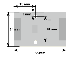
Dimensions of the MIPI Repeater Board