VC sensors for bending machines (press brake machines)
VC technical information for press brake controller Version 1.9.7
| Revision: | 1.1.0 |
|---|---|
| Date: | 2022-10-10 |
| Contact: | support@vision-comp.com |
| Copyright: | 1996-2022 Vision Components GmbH Ettlingen, Germany |
| Author: | VC Support, mailto:support@vision-comp.com |
This documentation has been prepared with most possible care. However Vision Components GmbH does not take any liability for possible errors. In the interest of progress, Vision Components GmbH reserves the right to perform technical changes without further notice.
Please notify support@vision-components.com if you become aware of any errors in this manual or if a certain topic requires more detailed documentation.
This manual is intended for information of Vision Component’s customers only. Any publication of this document or parts thereof requires written permission by Vision Components GmbH.
| Symbol | Meaning |
|---|---|
 |
The Light bulb highlights hints and ideas that may be helpful for a development. |
 |
This warning sign alerts of possible pitfalls to avoid. Please pay careful attention to sections marked with this sign. |
 |
This is a sign for an example. |
Trademarks
Linux, Debian, the Tux logo, Vivado, Xilinx and Zynq, ARM, Cortex, Windows XP, Total Commander, Tera Term, Motorola, HALCON, FreeRTOS, Vision Components are registered Trademarks. All trademarks are the property of their respective owners.
Table of Contents
- 1 Sensor type
- 2 IP address
- 3 Sensor mounting
- 4 Mounting Position X, R and Angle
- 5 Angle measurement test
- 6 Recommended Mounting Positions
- 7 Typical accuracy
- 8 Camera connectors
- 9 Strain gauges
- 10 OEM: GUI - VC Smart Shape
- 11 OEM: Communication steps for bending
- 12 OEM: Angle Measure Programs (ProductType)
- 13 OEM: Useful adjustable parameters for bending
- 14 Parameter error list
- 15 Troubleshooting
1 Sensor type
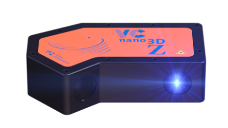
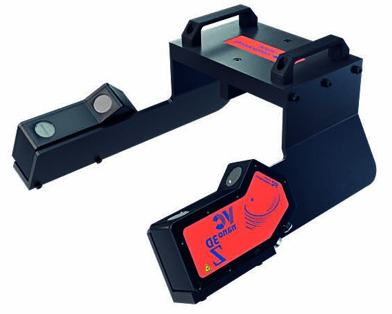
We recommend to use the „VC nano 3D Z 630 regular“ blue laser scanner. This sensor offers a large detection range for different dies without changing the mechanical position of the sensor.
VC nano 3D Z Series Operating Manual
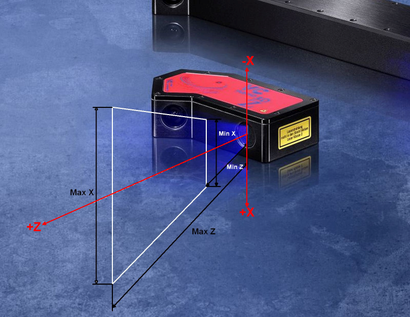
| Model (focal distance [mm] / angle [deg]) | (6/30) regular (recommended) | (6/30) large | (8/30) regular |
|---|---|---|---|
| Minimal distance Z [mm] | 80 | 150 | 95 |
| Maximal distance Z [mm] | 320 | 630 | 240 |
| Minimal distance X [mm] | 80 | 155 | 60 |
| Minimal distance C [mm] | 265 | 620 | 150 |
2 IP address
The standard IP of the sensors is: 192.168.3.15
Master port for machine: 1096
Slave port for debug: 1097
Typically you need two sensors – the front and back sensor. Every sensor must have a different IP address. Choose the IP address range which fits to your machine and is not already in use. You have to insert the IP addresses also in your press brake controller.
The sensor already comes with the latest software version.
In order to change the IP address or update the sensor software version please use the VC Update-Tool.
Please connect only one sensor at the beginning, as both sensors have the same IP address 192.168.3.15 and this will lead to routing problems.
Optional four sensors - two sensor pairs - are possible, if you have a long plate and you want to measure it on different positions (left and right). Normally this is not used as the OEM prefers a W-axis (sensor movement along the Y-axis direction).
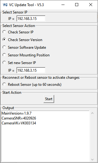
VC Update-Tool
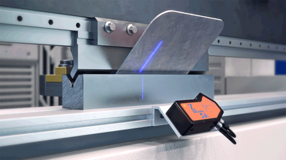
3 Sensor mounting
We recommend a mounting angle of around 30 degrees (20 to 50 is possible) to the vertical line for press brake machines.
If you stand in front of the machine take care that the front sensor is mounted this way, that the laser is on the left side and the camera lens on the right side (the VC logo is facing you, cable on right side).
The back sensor is mounted the same way. This means laser meets laser and camera lens faces camera lens.
Additionally the laser line of the front and back sensor should be at the same position (Y).
If necessary, set the sensor orientation for front and back Camera as "on the right side" at your press brake controller.
3.1 Measure Angle > 120 degrees
Try to mount your sensor perpendicular to your machine. Especially at large plate angles like 120 - 180 degrees (flat plate), the die reflected the laser line to the plate (also the other way around) and you get a double laser line, if the sensor is not mounted perpendicular. This more or less close double line biased the result angle.
Put a mirror on the die and check if you have a double laser line on the die. Try to improve the sensor mounting so that the reflected line is on identical position as the original line.
If the bend angle is smaller than 120 degrees this effect becomes less important, as the reflection is not that strong any more.
4 Mounting Position X, R and Angle
The camera mounting parameters X-Position, R-Position and Angle has to be very precise to your real sensor mounting position. Therefore we recommend to use the MDT (mounting detection tool) once.
You will need these mounting position values (X, R, Angle) as an input for your press brake controller.
Especially the Angle has to be very accurate as it has a direct influence to your output angle result.
Typical values for X, R and Angle are:
Front Sensor:
- X < 0, for example -110 mm
- R < 0, for example -40 mm
- Angle < 0, for example -30 degrees
Back Sensor:
- X > 0, for example +110 mm
- R < 0, for example -40 mm
- Angle > 0, for example +30 degrees
If you don’t know the mounting Angle of your sensor exactly, you have two options:
- Automatic detection of mounting position
- Manual detection of mounting position
Please have a look at the chapter Recommended Mounting Positions for the location of X, R and Angle.
4.1 Manual detection of mounting position
Try to determine the values X, R and Angle of both sensors as well as possible and use it as an input for the press brake controller. See drawings in chapter Recommended mounting positions for the position of X, R and Angle.
Then make a test bending to 90,0 degrees.
Measure the result angle with a separate tool at the same position as the laser measure the plate. If the result is for example 91,0 degrees you have to reduce your mounting angle settings of 1 degree.
For example Front sensor: original -30,0 degrees becomes -30,0 - 1,0 = -31,0 degrees for the new settings. Then bend again. The result angle should be now 90,0 degrees.
The parameters X- and R-position are not that critical. An accuracy of 0,5mm is sufficient. Both parameters refers to the centre of the laser beam lens. Please have a look at the technical drawings.
4.2 Automatic detection of mounting position
We recommend to use the MDT (mounting detection tool) in order to get the accurate mounting position of both sensors (X, R and Angle). Additionally with this tool, you can check, if every sensor works correctly.
Maybe your press brake controller has already implemented the automatic detection of the sensor mounting position X, R and Angle. Please ask your vendor.
If not, you can use the our VC Tools for detecting the parameters X, R and Angle: Angle Measure Tool
Or use the VC Update-Tool (repeat it for every sensor).
VC Press Break Mounting Detection Tool
Do the following steps:
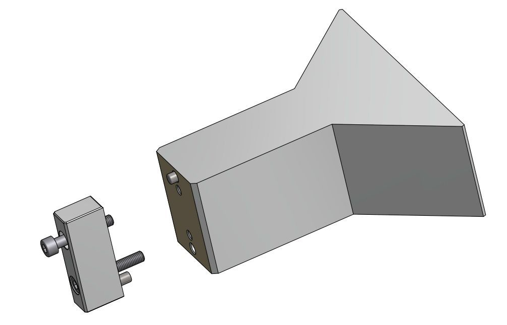
- mount in front of the laser beam the VC Press Break Mounting Detection Tool (MDT) from Vision Components (VK000563 / VC PB-MDT)
- select “Sensor Mounting Position” at your controller or our VC Tools and start the measuring. Maybe repeat it in order to see if the values are stable
- check if Phi from the output string is in the range 135,0 +/- 0.3 degrees. Then the sensor works fine. Otherwise check if the sensor can’t see the full range of the MDT. See later in this chapter
- transfer the values (X, R and Angle) to your press brake controller. Maybe you have to add an offset to R. See later in this chapter.
- do it for both sensors (front and back sensor IP)
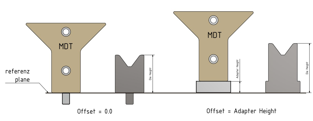
Take care of the correct reference plane. It has to be the same as for your V-Die height. If you use an Adapter block(60 x 60 x 20), then set the correct offset (Adapter Height) at your controller OR add the offset to the value R: R_controller = R_measured + Adapter_Height, e.g. R_controller = -40+20=-20.
In order to get stable results, please take care that the sensor sees both regions (MDT_LenLine0_MM and MDT_LenLine1_MM) completely (full selected length). For our recommended mounting positions V6-V70 and V6-V160 it is already the case.
If you cannot use the 13 x 20 mm sliding block, you can develop your own adapter block that fits to your machine.
5 Angle measurement test
For testing purpose and measuring the MDT, you can download a simple angle measure tool: Angle Measure Tool
Then do the following steps:
- set both sensor IPs to your environment
- start “Check Sensor IP” and test if both sensors are working
- mount the MDT (mounting detection tool) in front of the laser beam (the cables of both sensors are on the right side, if you stand in front of the machine)
- start “Get Sensor Mounting Position”. The values X, R and Angle are later for the controller settings. The value Phi should be in the range 135,0 +/- 0.3 degrees, then the sensor works fine
- if you use an MDT adapter, change the Adapter Offset value in the tool (offset = adapter height)
- start “Measure MDT (90 degrees)”. The result should be 90 degrees.
- now mount your V-Die and select the same V-Die at “Set V-Die Size [mm]”. You also can add a new one if you can’t find a fitting V-Die. Only symmetric V-Dies are possible with this tool.
- put a plate inside your V-Die and start “Measure Plate Angle”. Check if the selected LML (measure length) is available. The output value “DetLen=” should be at least as long as LML. Then the sensor could see and detect the entire selected measure length LML.
- If necessary transfer the X, R and Angle for both sensors to your controller
- last but not least, reboot the sensor (power reset) and initialize the sensors at your controller, so that they are connected again to your machine
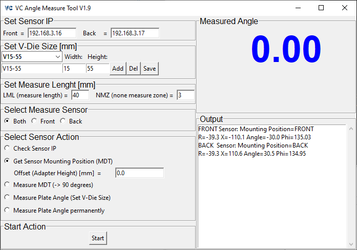
Angle measure tool GUI
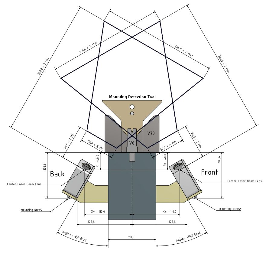
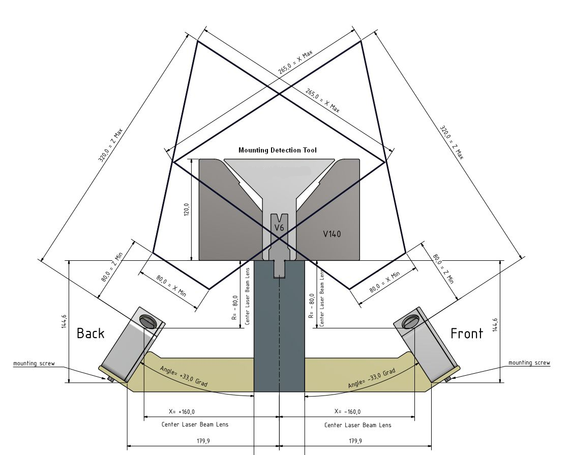
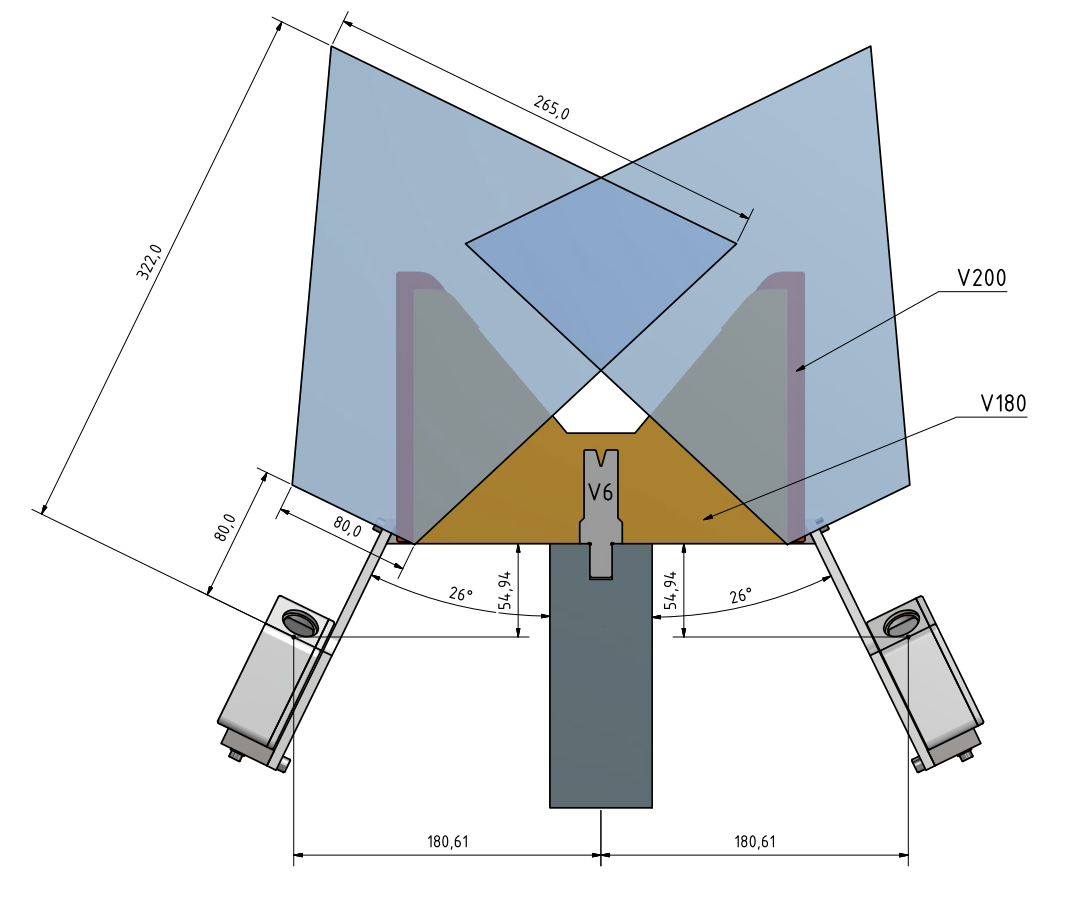
6 Recommended Mounting Positions
You only need the standard sensor VC nano 3D Z 630 regular. For the large range of dies V6 – V200 we recommend the following mounting positions. They are also available as portable versions:
- VK000560 / VC PB-PMK (portable mounting kit) V6 - V70 / 30°
- VK000562 / VC PB-PMK (portable mounting kit) V6 - V160 / 33°
- VK000441 / VC PB-PMK (portable mounting kit) V60 - V200 / 26°
VC Portable Mounting Kit
Please select the typical range you need. For smaller ranges you can put the sensor closer to the plate, which leads to a higher accuracy. Please refer to the chapter Typical Accuracy.
7 Typical accuracy
The measure accuracy depends on the measure distance. The closer the better. For a typical accuracy, please measure the distance from the “Center Laser Beam Lens” to the plate. The accuracy depends also on the measure length on the plate and the material of the plate. Please have a look at the table below.
Model: VC nano 3D Z 630 regular:
| Distance Z [mm] | 80 | 90 | 100 | 110 | 120 | 130 | 140 | 150 | 160 | 170 | 180 | 190 | 200 | 210 | 220 | 230 | 240 | 250 | 260 | 270 | 280 | 290 | 300 | 310 | 320 |
|---|---|---|---|---|---|---|---|---|---|---|---|---|---|---|---|---|---|---|---|---|---|---|---|---|---|
| Delta Phi [degrees] | 0.02 | 0.02 | 0.03 | 0.03 | 0.04 | 0.05 | 0.05 | 0.06 | 0.07 | 0.07 | 0.08 | 0.09 | 0.09 | 0.10 | 0.11 | 0.11 | 0.12 | 0.13 | 0.13 | 0.14 | 0.15 | 0.15 | 0.16 | 0.17 | 0.17 |
| Detection points | 429 | 396 | 367 | 343 | 321 | 303 | 286 | 271 | 257 | 245 | 234 | 224 | 214 | 206 | 198 | 190 | 184 | 177 | 171 | 166 | 161 | 156 | 151 | 147 | 143 |
| Distance Z [mm] | 80 | 90 | 100 | 110 | 120 | 130 | 140 | 150 | 160 | 170 | 180 | 190 | 200 | 210 | 220 | 230 | 240 | 250 | 260 | 270 | 280 | 290 | 300 | 310 | 320 |
|---|---|---|---|---|---|---|---|---|---|---|---|---|---|---|---|---|---|---|---|---|---|---|---|---|---|
| Delta Phi [degrees] | 0.02 | 0.03 | 0.04 | 0.05 | 0.06 | 0.07 | 0.08 | 0.09 | 0.10 | 0.11 | 0.12 | 0.13 | 0.14 | 0.15 | 0.16 | 0.17 | 0.18 | 0.19 | 0.20 | 0.21 | 0.22 | 0.23 | 0.24 | 0.25 | 0.26 |
| Detection points | 286 | 264 | 245 | 229 | 214 | 202 | 190 | 180 | 171 | 163 | 156 | 149 | 143 | 137 | 132 | 127 | 122 | 118 | 114 | 111 | 107 | 104 | 101 | 98 | 95 |
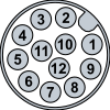
8 Camera connectors
For more technical details please have a look at the Hardware documentation of the 3D Laser Triangulation Sensor at our homepage.
| Camera Socket Rear View | Pin | Signal | Level | Cable Standard Color |
|---|---|---|---|---|
 |
1 | Main Power Supply | +24 V | brown |
| 2 | Common Ground | GND | blue | |
| 3 | INP 0 or Laser Enable | +5–24 V | white | |
| 4 | OUT 0 | +24 V | green | |
| 5 | INP 1 or ENC Z or Trigger Enable | +5–24 V | pink | |
| 6 | OUT 1 | +24 V | yellow | |
| 7 | OUT 2 | +24 V | black | |
| 8 | INP 2 or ENC A or TrigIn | +5–24 V | grey | |
| 9 | OUT 3 or TrigOut [1] | +24 V | red | |
| 10 | INP 3 or ENC /B | +5–24 V | purple | |
| 11 | INP 4 or ENC B | +5–24 V | grey/pink | |
| 12 | INP 5 or ENC /A | +5–24 V | red/blue |
| [1] | TrigOut only supported at custom OEM versions. |
All outputs are high-side switches, 24V, 400mA max.
All inputs and encoder inputs are 5-24V, 3mA, 200kHz max.
| Camera Socket Rear View | Pin | Signal |
|---|---|---|
 |
1 | ETH_A_p |
| 2 | ETH_A_n | |
| 3 | ETH_B_p | |
| 4 | ETH_B_n | |
| 5 | ETH_D_p | |
| 6 | ETH_D_n | |
| 7 | ETH_C_n | |
| 8 | ETH_C_p |
9 Strain gauges
Strain-gauges are not necessary but optional. They can improve the measurement of the spring back angle.
Strain-gauges are recommended to prevent that the product tilts after the spring back measurement and get a double bend line. This is very important if you want to measure with on sensor only (front or back sensor).
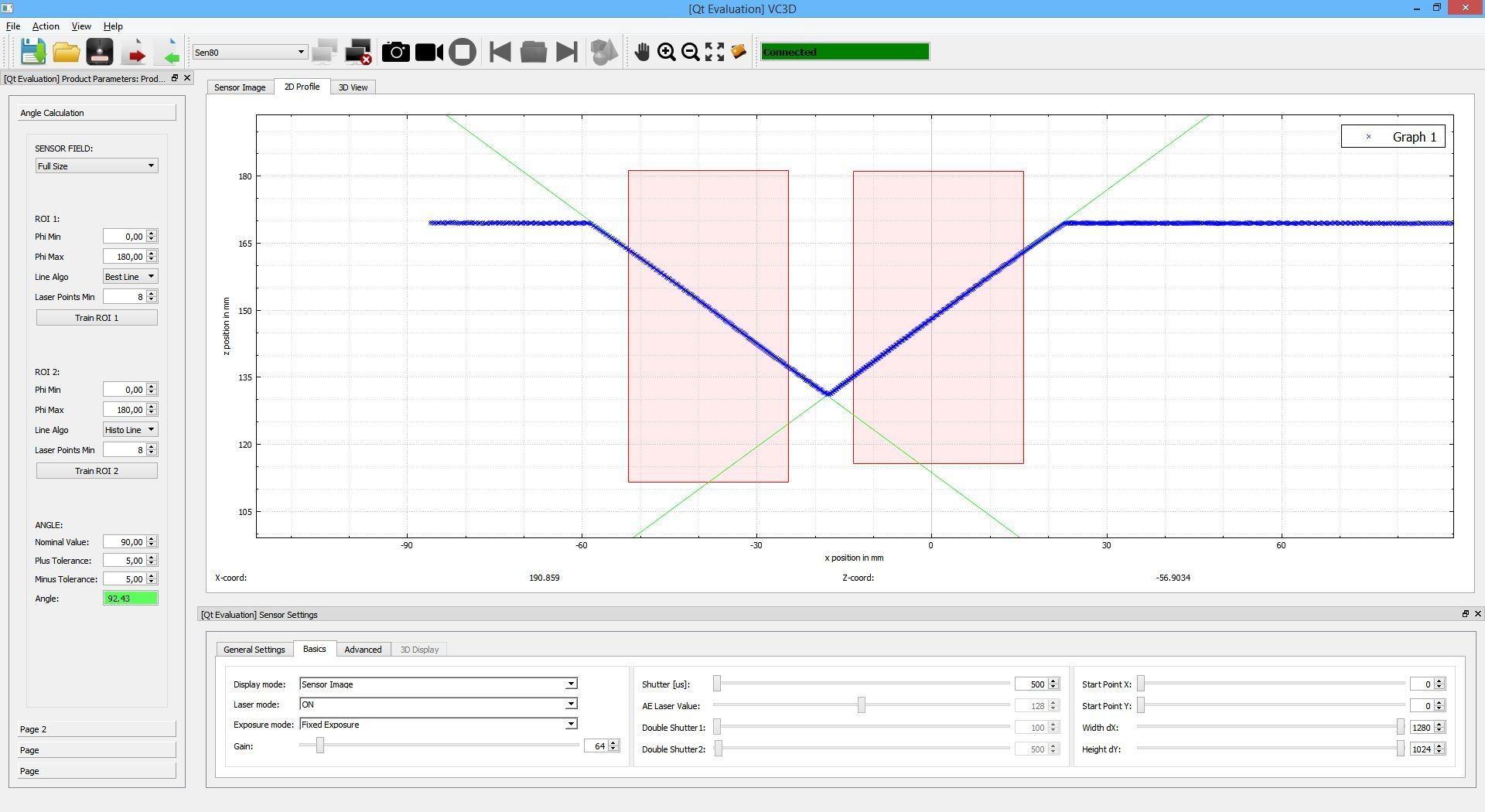
10 OEM: GUI - VC Smart Shape
Expert debug tool:
ATTENTION: VC Smart Shape will change parameters – reset sensor after using VC Smart Shape in order to switch back to the standard sensor parameters (power reset)!
For displaying the attitude profile, grey images or changing sensor parameters, please use the Windows GUI "VC Smart Shape" to communicate with the sensor:
In order to see the results parallel to the machine process, use the slave port 1097 for the GUI. The machine will use port 1096.
For best angle results, select:
- Line Algo: Combination
- Phi Filter: 1
11 OEM: Communication steps for bending
Please refer to the documentation “VC nano 3D Z Laser Scanner - Manual Version x.x.x” how to send string commands to the sensor (Communication Protocol between Host and Sensor).
You can send all parameters in one string. Just terminate every parameter by Line Feed (0x0A) or NULL (0x00) or “n”.
11.1 Sensor Initialisation
Send once after sensor start up (initialisation) the following parameters (for a clear defined start):
Product Parameter (CMD_RECEIVE_PRODUCT_DATA - ID 40):
      AdjustSensorRoi = 2 # or 1 for max. speed

      J00_ProductType = 0
      J01_ProductType = 0
      J02_ProductType = 0
      J03_ProductType = 0

     J00_LineAlgoMode = 2
J00_MaxLineDisBestFit = 1.0
   J00_BestLineFilter = 100
  J00_HistoLineFilter = 1
           J00_PhiMin = 0.0
Sensor Parameters (CMD_RECEIVE_SENSOR_DATA - ID 43):
          DataMode = 8
          NbrLines = 0
       ShutterTime = 50
           GainVal = 0
         LaserMode = 1
         RlcThresh = 10
       LaserSelect = 0
          OptWidth = 8
          MinWidth = 2
          MaxWidth = 30
   SpeckleFilterDx = 5
   SpeckleFilterDy = 3
   LaserMaskFilter = 31
   ReflexionFilter = -1
         ROI_X_PIX = 0
         ROI_Y_PIX = 0
        ROI_DX_PIX = 1408
        ROI_DY_PIX = 1080
     AdjustSenHmax = 0
       TriggerMode = -1
    TriggerDelayNs = 0
      ExposureMode = 1
    AutoShutterVal = 128
 AutoShutterFilter = 0
    AutoShutterMin = 1
    AutoShutterMax = 100
       AutoGainMin = 0
       AutoGainMax = 300
    DoubleShutter1 = 5
    DoubleShutter2 = 20
    TripleShutter3 = 100
    EthernetPackNr = 1
    AutoTriggerFPS = 50.0 # or 100 for 100 frames (angles) per second
  AutoTriggerError = 0
EthernetSendNoWait = 1
      MedianFilter = 7
         SensorLUT = 0
 TransferAllPos_MM = 0
11.2 Angle measurement
If you want to measure angles send the following parameters:
Product Parameter (CMD_RECEIVE_PRODUCT_DATA - ID 40):
        J00_ProductType = 1
          J00_PolygonNr = 2
J00_PolygonPoint_X00_MM = -500.0
J00_PolygonPoint_Z00_MM =    0.0
J00_PolygonPoint_X01_MM =  500.0
J00_PolygonPoint_Z01_MM =  500.0
Sensor Parameters (CMD_RECEIVE_SENSOR_DATA - ID 43):
DataMode = 8
NbrLines = -1
You will permanently get a result strings like:
JOB 0.0001: Phi=156.36 Cx=00.4011 Cy=-0.9161 B=-0104.19 LAlgo=2 Points=0501 DetLen=042.6 Filter=100 dPhi=0.03 Error=0 Sh=0012us Gain=000 TimeStamp=0000006468167ms
For accuracy reason ignore the first 5-10 angles after a new plate or ROI is defined, as the auto exposure takes some images for adaption.
11.3 Stop angle measurement
If you want to stop measure angles send the following parameters:
Sensor Parameters (CMD_RECEIVE_SENSOR_DATA - ID 43):
NbrLines = 0

OR

Use the "STOP" command (CMD_STOP 0).
Later we will adapt the ROI (region of interest) parameter that it fits to the V-die. See following chapter.
J00_PolygonPoint_X00_MM = -500.0
J00_PolygonPoint_Z00_MM =    0.0
J00_PolygonPoint_X01_MM =  500.0
J00_PolygonPoint_Z01_MM =  500.0
For that you have to know the mounting position (R, X and Angle) of the individual sensor.
12 OEM: Angle Measure Programs (ProductType)
By sending different Product and Sensor Parameters to the camera you can activate different Jobs and Tasks (ProductType).
For example:
- ProductType 1002: Measure the MDT (mounting detection tool) and give the values R, X, Angle
- ProductType 1: Measure the angle in a ROI (region of interest)
- ProductType 0: Do nothing
To start a job do the following steps:
- stop the sensor from the actual job (CMD_STOP)
- put the plate material or MDT (depending on the job) inside the machine
- send the product parameters to the sensor (CMD_RECEIVE_PRODUCT_DATA)
- send the sensor parameters to the sensor (CMD_RECEIVE_SENSOR_DATA)
- receive the results (the camera sends results after every scan until you stop it)
- maybe ignore the first 5 - 10 angles, as they are not that accurate because of auto exposure adaption
Set the necessary step (parameter ID) with the STRING command:
| Parameter ID | ID | Effect |
|---|---|---|
| CMD_STOP | 0 | Stop image acquisition and set NbrLines to 0 |
| CMD_RECEIVE_PRODUCT_DATA | 40 | Send product parameter from Host to Camera |
| CMD_RECEIVE_SENSOR_DATA | 43 | Send sensor parameter from Host to Camera |
It is possible to send one, more or all parameters in one “STRING” command. Just terminate every parameter by Line Feed (0x0A) or NULL (0x00) or “n”.
Attention: Please take care, that you send the parameters to both sensors (front and back) by using the individual sensor IP.
Optional:
Instead of sending the different parameter settings all the time, you can predefine the main parameters in a sensor and product file.
But we recommend to send all the parameters every time, as it takes barely longer and is less error-prone.
The sensor parameters at: /etc/vcnano3dz-server/VC3DPar.txt
The product parameters at: /etc/vcnano3dz-server/ProdPar.txt
If necessary, you can do one or up to four jobs in one scan (J00 .. J03).
12.1 Measure X, R and Angle with the MDT (ProductType 1002)
Before you start the detection, please mount in front of the laser beam the VC Press Break Mounting Detection Tool from Vision Components (VK000563 / VC PB-MDT (mounting detection tool).
Please have a look at chapter Automatic detection of mounting position.
For an easy detection of the MDT (mounting detection tool) use the following parameters.
Measure the MDT at least 10 times in order to give the auto shutter mode time to fit the laser brightness.
Then you can use the output values.
12.1.1 Necessary parameters (ProductType 1002)
Product Parameters:
        J00_ProductType = 1002
          J00_PolygonNr = 2
J00_PolygonPoint_X00_MM = -500.0
J00_PolygonPoint_Z00_MM = 0.0
J00_PolygonPoint_X01_MM = 500.0
J00_PolygonPoint_Z01_MM = 500.0

Maybe some more parameters. See chapter OEM: Useful adjustable parameters for bending.
Sensor Parameters:
DataMode = 8
NbrLines = -1

Maybe some more parameters. See chapter OEM: Useful adjustable parameters for bending.
12.1.2 Sensor result output of the MDT detection (ProductType 1002)
Front Sensor:
JOB 0.1002: Position=FRONT R=-61.3 X=-100.3 Angle=-28.04 [-20.0..-50.0] xC=003.2 yC=153.9 Phi=134.95 Error=0 Sh=0033us Gain=000 TimeStamp=0000008748009ms
Back Sensor:
JOB 0.1002: Position=BACK R=-61.4 X=0101.5 Angle=030.77 [ 20.0.. 50.0] xC=003.1 yC=154.5 Phi=134.93 Error=0 Sh=0033us Gain=000 TimeStamp=0000008849994ms
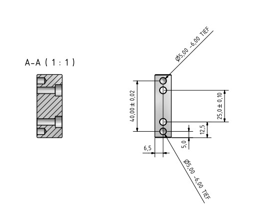
Description of MDT:
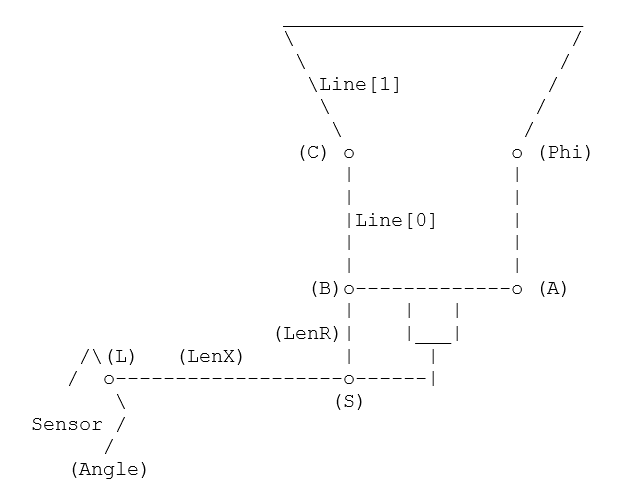
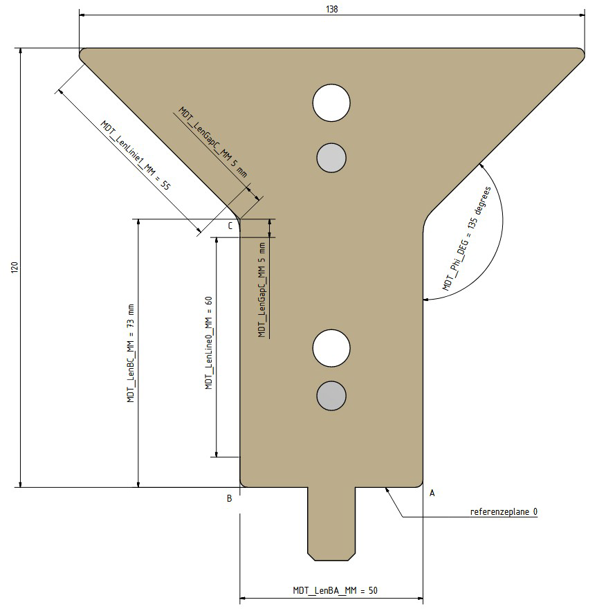
L:     laser beam centre (0|0)
Angle: angle of the scanner
LenX:  x distance of the scanner to the centre of the MDT tool
S:     cross point of line Line[0] and the perpendicular line LS
C:     cross point of die line (Line[0]) and angle line (Line[1])
LenBA: width of the MDT tool

Output:

R     = length of distance BS
X     = x distance from Point L (position (0|0)) and centre of MDT tool
Angle = sensor mounting angle
Phi   = angle of the MDT (135,0 +/- 0.2 degrees)
Maybe display the Phi value (front and back) in order to see if the sensor works fine.
12.2 Measure the Angle in a rectangle ROI (ProductType 1)
12.2.1 Calculating the ROI (ProductType 1 - rectangle ROI)
- NMZ = None measure zone [mm]
- LML = Laser measure length [mm]
- DieX = DieWidth / 2
- DieY = DieHeight (from reference line R = 0)
| Back Sensor (Angle > 0, DieX > 0) | Front Sensor (Angle < 0, DieX < 0) | |
|---|---|---|
| Len1 = (NMZ) / cos(Angle) Len2 = (NMZ + LML) / cos(Angle) | Len1 = (NMZ) / cos(Angle) Len2 = (NMZ + LML) / cos(Angle) | |
| P0x | DieX + Len2 | DieX - Len2 |
| P0y | DieY | DieY |
| P1x | DieX - LML * cos(Angle) | DieX + LML * cos(Angle) |
| P1y | DieY + Len2 / tan(Angle) - LML * sin(Angle) | DieY - Len2 / tan(Angle) + LML * sin(Angle) |
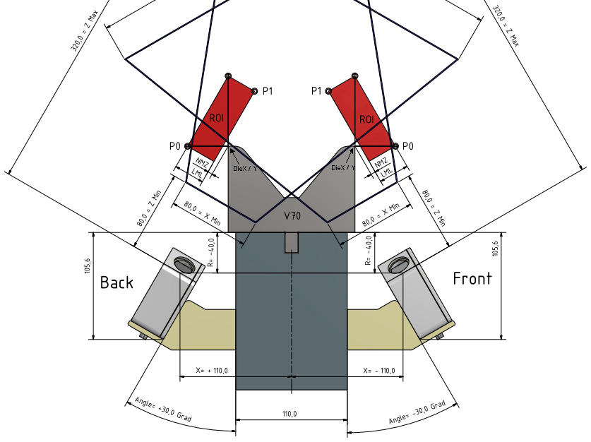
12.2.2 Necessary parameters (ProductType 1 - rectangle ROI)
P0 and P1 are opposite points of the rectangle ROI.
Up to 4 jobs (J00-J03) at one image acquisition are possible (e. g. angle measurements in 4 ROIs). Typically you only need J00.
Product Parameters:
        J00_ProductType = 1
          J00_PolygonNr = 2
J00_PolygonPoint_X00_MM = S0x (Converted P0x, see 11.4 for converting)
J00_PolygonPoint_Z00_MM = S0y (Converted P0y)
J00_PolygonPoint_X01_MM = S1x (Converted P1x)
J00_PolygonPoint_Z01_MM = S1y (Converted P1y)

Maybe some more parameters. See chapter OEM: Useful adjustable parameters for bending.
Sensor Parameters:
               DataMode = 8
               NbrLines = -1

Maybe some more parameters. See chapter OEM: Useful adjustable parameters for bending.
12.2.3 Sensor result output of the angle detection (ProductType 1 - rectangle ROI)
JOB 0.0001: Phi=156.36 Cx=00.4011 Cy=-0.9161 B=-0104.19 LAlgo=2 Points=0501 DetLen=042.6 Filter=100 dPhi=0.03 Error=0 Sh=0012us Gain=000 TimeStamp=0000006468167ms


Job:                job number followed by ProductType
Phi:                measured line angle [°]
Cx, Cy, B:          general straight line equation
LAlgo:              line algorithm mode (2 = combination of hough and best line)
Points:             detected laser points
DetLen:             measured line length [mm]
Filter:             use x% of the closest detection points to the line for best line calculation
dPhi:               expected angle accuracy
Error:              error number
Sh:                 used shutter time [µs]
Gain:               used gain value
TimeStamp:          image acquisition time since camera power on [ms]
12.3 Optional - Measure Angle in polygon ROI (ProductType 1)
12.3.1 Calculating the ROI (ProductType 1 - polygon ROI)
- NMZ = None measure zone [mm]
- LML = Laser measure length [mm]
- Len = (W + NMZ + LML) / cos(22.5°)
| Back Sensor (Angle > 0, DieX > 0) | Front Sensor (Angle < 0, DieX < 0) | |
|---|---|---|
| P0x | DieX + NMZ | DieX - NMZ |
| P0y | DieY | DieY |
| P1x | DieX + Len | DieX - Len |
| P1y | DieY | DieY |
| P2x | DieX + Len * cos(45°) | DieX - Len * cos(45°) |
| P2y | DieY + Len * cos(45°) | DieY + Len * cos(45°) |
| P3x | DieX - W | DieX + W |
| P3y | DieY + Len | DieY + Len |
| P4x | DieX - W | DieX + W |
| P4y | DieY + NMZ + W | DieY + NMZ + W |
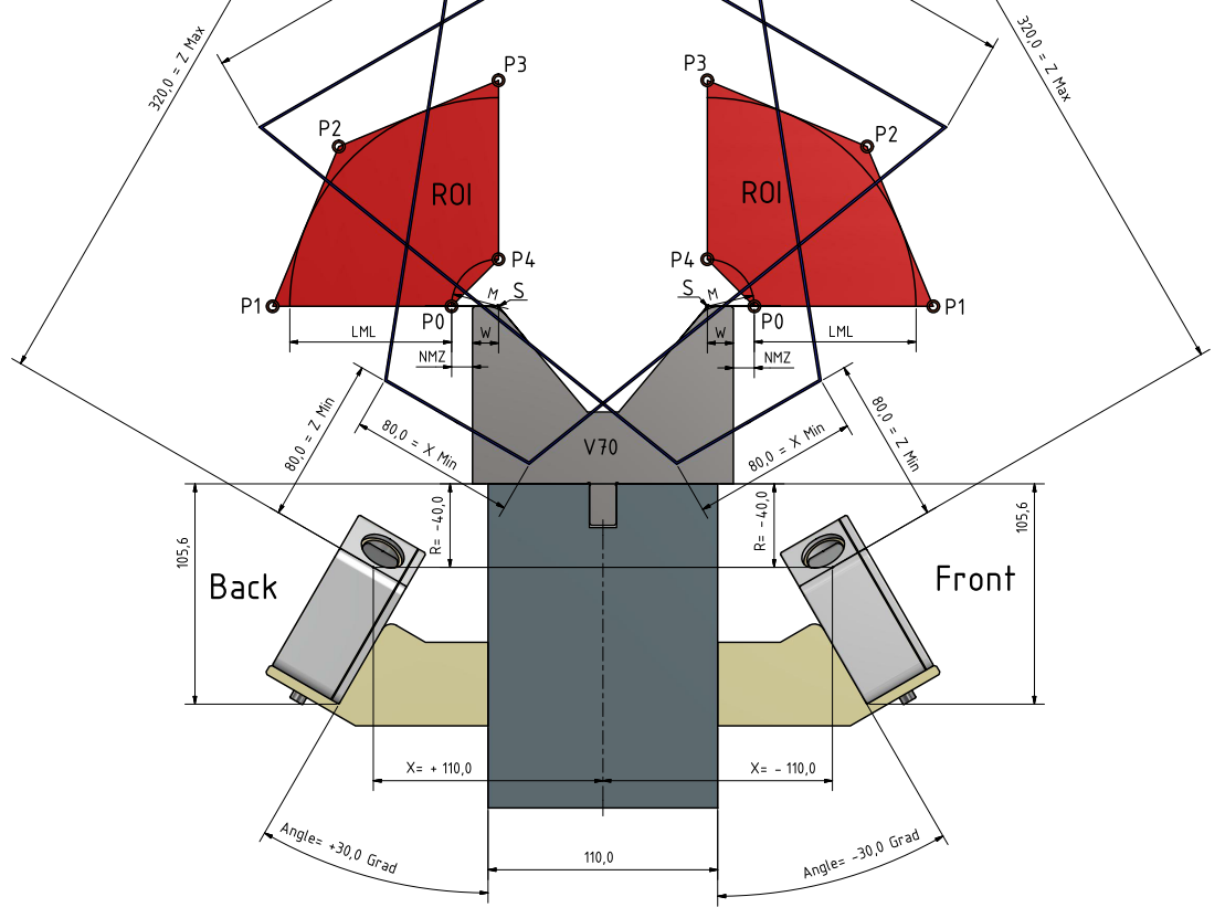
12.3.2 Necessary parameters (ProductType 1 - polygon ROI)
Up to 8 polygon points (J00_PolygonNr) are possible.
Up to 4 jobs (J00-J03) at one image acquisition are possible (e. g. angle measurements in 4 ROIs). Typically you only need J00.
Product Parameter:
        J00_ProductType = 1
          J00_PolygonNr = 5
J00_PolygonPoint_X00_MM = S0x (Converted P0x, see 11.4 for converting)
J00_PolygonPoint_Z00_MM = S0y (Converted P0y)
J00_PolygonPoint_X01_MM = S1x (Converted P1x)
J00_PolygonPoint_Z01_MM = S1y (Converted P1y)
J00_PolygonPoint_X02_MM = S2x (Converted P2x)
J00_PolygonPoint_Z02_MM = S2y (Converted P2y)
J00_PolygonPoint_X03_MM = S3x (Converted P3x)
J00_PolygonPoint_Z03_MM = S3y (Converted P3y)
J00_PolygonPoint_X04_MM = S4x (Converted P4x)
J00_PolygonPoint_Z04_MM = S4y (Converted P4y)

Maybe some more parameters. See chapter OEM: Useful adjustable parameters for bending.
Sensor Parameter:
               DataMode = 8
               NbrLines = -1

Maybe some more parameters. See chapter OEM: Useful adjustable parameters for bending.
12.3.3 Sensor result output of the angle detection (ProductType 1 - polygon ROI)
JOB 0.0001: Phi=156.36 Cx=00.4011 Cy=-0.9161 B=-0104.19 LAlgo=2 Points=0501 DetLen=042.6 Filter=100 dPhi=0.03 Error=0 Sh=0012us Gain=000 TimeStamp=0000006468167ms


Job:                job number followed by ProductType
Phi:                measured line angle [°]
Cx, Cy, B:          general straight line equation
LAlgo:              line algorithm mode (2 = combination of hough and best line)
Points:             detected laser points
DetLen:             measured line length [mm]
Filter:             use x% of the closest detection points to the line for best line calculation
dPhi:               expected angle accuracy
Error:              error number
Sh:                 used shutter time [µs]
Gain:               used gain value
TimeStamp:          image acquisition time since camera power on [ms]
12.4 Converting Machine Coordinates to Sensor Coordinates
You will need the mounting values R, X and Angle of the individual sensor.
x = MachineX - X
y = MachineY - R

// rotation matrix from machine coordinates (centre of die holder) to sensor coordinates
SensorX =  cos(Angle) * x +  sin(Angle) * y
SensorY =  -sin(Angle) * x + cos(Angle) * y
Example Values (rectangle ROI):
P = Machine Coordinate Points
S = Sensor Coordinate Points
See chapter Angle Measurement for calculation.
Back: DieHeight=65.00 DieWidth=80.00 LML=30.00 NMZ=3.00 X=110.00 R=-40.00 Angle=23.40 → P0x=75.96 P0y=65.00 P1x=12.47 P1y=136.18 S0x=10.46 S0y=109.88 S1x=-19.54 S1y=200.42
Front: DieHeight=65.00 DieWidth=80.00 LML=30.00 NMZ=3.00 X=-105.00 R=-40.00 Angle=-22.40 → P0x=-75.69 P0y=65.00 P1x=-12.26 P1y=140.17 S0x=-12.92 S0y=108.25 S1x=17.08 S1y=201.91
12.5 Calculate Plate Angle
Plate Angle could be measured in range [0° .. 240°], typical [30° .. 180°]. 180° is a flat plate.
12.5.1 Two sensor detection (recommended)
if X_Front < 0 AND X_Back > 0: # mounting both sensor cables right (recommended way)
PlateAngle = –(SensorAngleFront – MountingAngleFront) + (SensorAngleBack - MountingAngleBack)

if X_Front > 0 AND X_Back < 0: # mounting both sensor cables left
PlateAngle = (SensorAngleFront – MountingAngleFront) - (SensorAngleBack - MountingAngleBack)

if X_Front < 0 AND X_Back < 0: # mounting front sensor cable right, back sensor cable left
PlateAngle = –(SensorAngleFront – MountingAngleFront) - (SensorAngleBack – MountingAngleBack) + 180

if X_Front > 0 AND X_Back > 0: # mounting front sensor cable left, back sensor cable right
PlateAngle = (SensorAngleFront – MountingAngleFront) + (SensorAngleBack – MountingAngleBack) - 180

if PlateAngle < 0: PlateAngle + 360
if PlateAngle > 240: PlateAngle - 180
12.5.2 Front sensor detection (not accurate, if plate is asymmetric)
if X_Front < 0: PlateAngle = -2 * (SensorAngleFront – MountingAngleFront) + 180
else: PlateAngle = 2 * (SensorAngleFront – MountingAngleFront) - 180

if PlateAngle < 0: PlateAngle + 360
if PlateAngle > 240: PlateAngle - 180
12.5.3 Back sensor detection (not accurate, if plate is asymmetric)
if X_Back > 0: PlateAngle = 2 * (SensorAngleBack – MountingAngleBack) - 180
else: PlateAngle = -2 * (SensorAngleBack – MountingAngleBack) + 180

if PlateAngle < 0: PlateAngle + 360
if PlateAngle > 240: PlateAngle - 180
13 OEM: Useful adjustable parameters for bending
Attention: Please take care, if you make some sensor or product parameters adjustable, then send them also to the sensor (together with the “Necessary Parameters”).
| VC parameter name | Default | MinVal | MaxVal | Explanation |
|---|---|---|---|---|
| Measure Mode | 0 | 0 | 2 | 0=Both 1=Front 2=Back Sensor for plate angle |
| VC parameter name | Default | MinVal | MaxVal | Explanation |
|---|---|---|---|---|
| NMZ | 3 | 0 | 40 | No measurement zone [mm] |
| LML | 30 | 5 | 80 | Laser measure length [mm] |
| VC parameter name | Default | MinVal | MaxVal | Explanation |
|---|---|---|---|---|
| Front sensor | ||||
| IP | x.x.x.x | IP address of sensor | ||
| X | < 0 | Sensor mounting [mm] | ||
| R | < 0 | Sensor mounting [mm] | ||
| Angle | < 0 | Sensor mounting angle [°] | ||
| Back sensor | ||||
| IP | x.x.x.x | IP address of sensor | ||
| X | > 0 | Sensor mounting [mm] | ||
| R | < 0 | Sensor mounting [mm] | ||
| Angle | > 0 | Sensor mounting angle [°] | ||
| AutoTriggerFPS | 50 | 10 | 400 | Exposure mode for image acquisition |
| ExposureMode | 1 | 0 | 3 | Frames per second [fps] (>174 fps limit sensor area) (useful 1 for standard and 3 for difficult materials) |
| (LaserSelect) | 0 | 0 | 2 | Laser line method (useful 0 and 1) |
| (ReflexionFilter) | -1 | -7 | 7 | Laser line detection filter mode (useful -1 and 1) |
| (AutoShutterFilter) | 0 | 0 | 6 | Auto shutter mode where laser brightness is based on |
| VC parameter name | Default | MinVal | MaxVal | Explanation |
|---|---|---|---|---|
| J00_MDT_LenBC_MM | 73 | 10 | 200 | MDT length from reference base line to centre of Phi |
| J00_MDT_LenBA_MM | 50 | 10 | 100 | MDT base width |
| (J00_MDT_Phi_DEG) | 135 | 30 | 180 | MDT Detection Angle Phi |
| (J00_MDT_LenLine0_MM) | 60 | 10 | 100 | MDT measure length of base part (from centre of Phi) |
| (J00_MDT_LenLine1_MM) | 60 | 10 | 100 | MDT measure length of top part (from centre of Phi) |
14 Parameter error list
| Error name | Error Number | Effect |
|---|---|---|
| ERR_NONE | 0 | Success |
| ERR_PROD_INACTIV | -4000 | Job was not executed |
| ERR_PROD_ROI_NR | -4001 | Less than expected ROI points |
| ERR_PROD_ANGLE | -4002 | No line in selected angle range |
| ERR_PROD_LINE_NR | -4003 | Less than expected points for line |
| ERR_PROD_GENERAL | -4004 | General product calculation error |
| ERR_PROD_RESULT | -4005 | Couldn't calculate product result |
15 Troubleshooting
15.1 Angle accuracy
In any case of angle accuracy problems, please do the following steps:
- Carefully clean both glasses of the sensors. Do not make any scratches on the surface.
- Check with the MDT (mounting detection tool) if both sensors work correct. See chapter Angle Measurement Test. Take care, that the laser and the field of view of the sensor is not blocked by any mechanical parts. Then Phi should be in the range 135,0 +/- 0.3 degrees.
Now both sensors are fine. The problem must be in the settings. Please check your controller settings:
- Are the values for X, R and Angle correct transferred to your controller (including sign)?
- Did you use an MDT Adapter and did you set the correct Adapter Offset at your controller? See chapter Automatic detection of mounting position with the MDT.
- Is the correct V-Die selected?
- Could both sensors see the plate (laser and field of view of the sensor is not blocked).
- Is the plate long enough for the selected laser measure length (LML)?
- Some controller needs the correct settings of the sensor mounting position (cables right or left).
- Inaccurate angles
15.2 Constant Angle Offset
If you always have a constant plate angle result offset, than change the value of the mounting “Angle” at your controller. If the result is 91,0 degrees (open angle, instead of 90,0 degrees) you have to decrease your mounting angle settings of 1,0 degree. For example Front sensor: original -30,0 degrees becomes -30,0 - 1,0 = -31,0 degrees as a new setting. Then bend again. The result angle should be now 90,0 degrees.
15.3 Communication Error
In an industrial environment take care of the electromagnetic compatibility (EMC). Use Ethernet cables which are at least Cat5e and well shielded.
15.4 Unstable angle results
The main challenge is the measurement of the spring back angle. If the results are unstable, try to improve the controller settings for the spring back angle calculation.
15.5 Bad angle results using only one sensor
When the plate part is unbalanced, it will inevitably fall on one side, in that case we advise using strain gauges.
15.6 Mechanical sensor crash
Check the accuracy of the sensor with the MDT (mounting detection tool). Phi should be in the range 135,0 +/- 0.3 degrees. If not, change the sensor and don’t forget to adapt the IP address of the new sensor.
15.7 Can’t get the values (X, R, Angle) of the MDT (mounting detection tool) or Error -4000
Check if the sensor has at least version 1.9.7.